
TM 5-3805-248-23-1
DIFFERENTIAL LOCK PEDAL REPLACEMENT - CONTINUED
0171 00
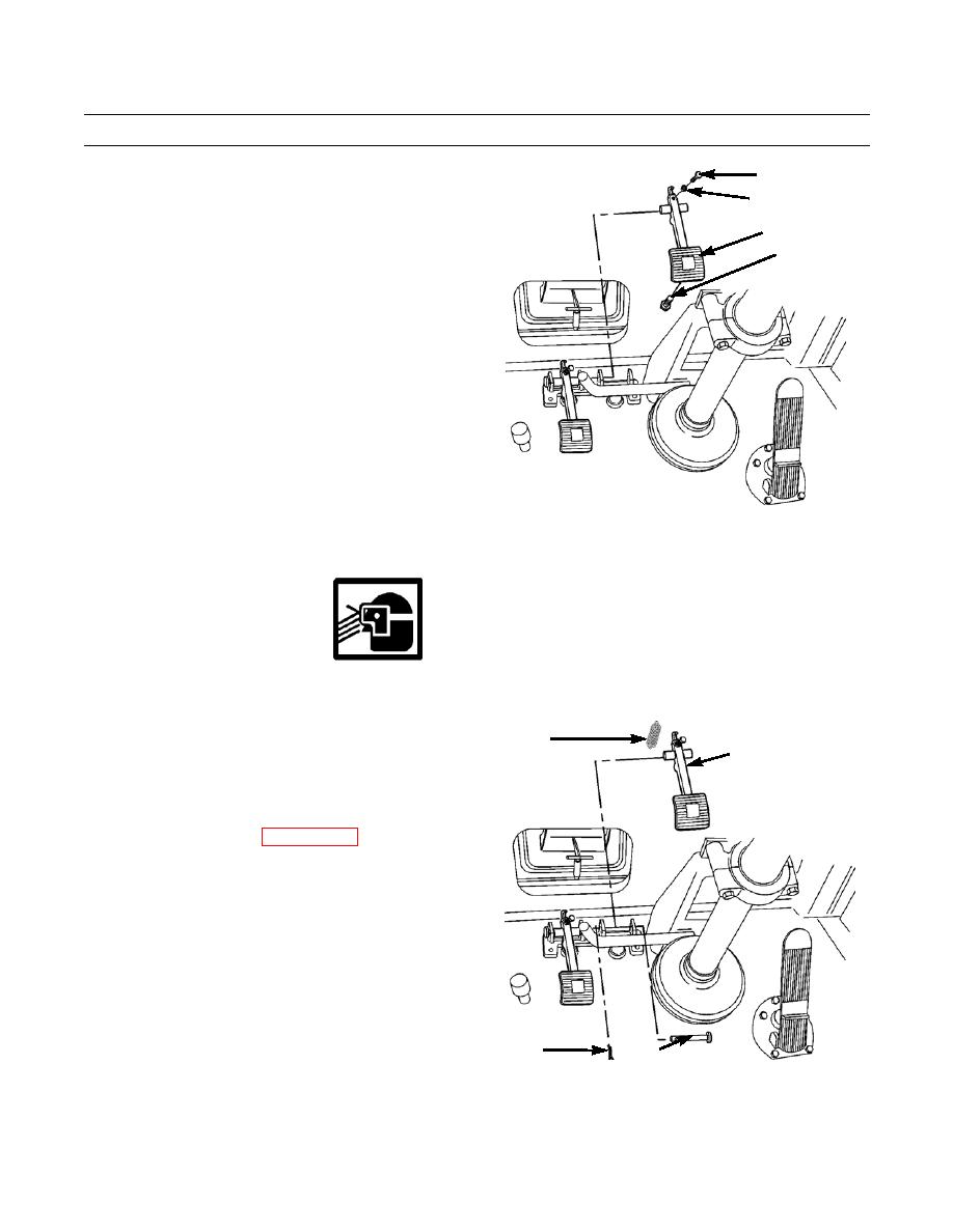
REMOVAL - CONTINUED
4
2.
Remove lock bolt (7), bolt (4) and nut (5) from
5
pedal (6).
6
7
394-903
INSTALLATION
WARNING
Some components are under spring tension. Wear eye protection and use caution during disassembly to
avoid injury.
1.
Install nut (5) and bolt (4). Tighten bolt only until
1
threads protrude through pedal (6).
PEDAL ASSEMBLY
2.
Install lock bolt (7).
3.
Install pedal assembly, spring (1), pin (2) and new cot-
ter pin (3).
4.
Adjust pedal and valve (WP 0173 00).
5.
Operate machine to verify correct differential lock
pedal operation (TM 5-3805-248-10).
3
2
394-902
END OF WORK PACKAGE
0171 00-2

