
TM 5-3805-248-23-2
CONTROL LEVER LINKAGE REPLACEMENT - CONTINUED
0325 00
INSTALLATION - CONTINUED
NOTE
Steps 9 through 12 are the maintenance procedure for the installation of the ejector lever linkage seg-
ment from support to remote lever bracket. The maintenance procedure for the apron lever linkage seg-
ment is identical.
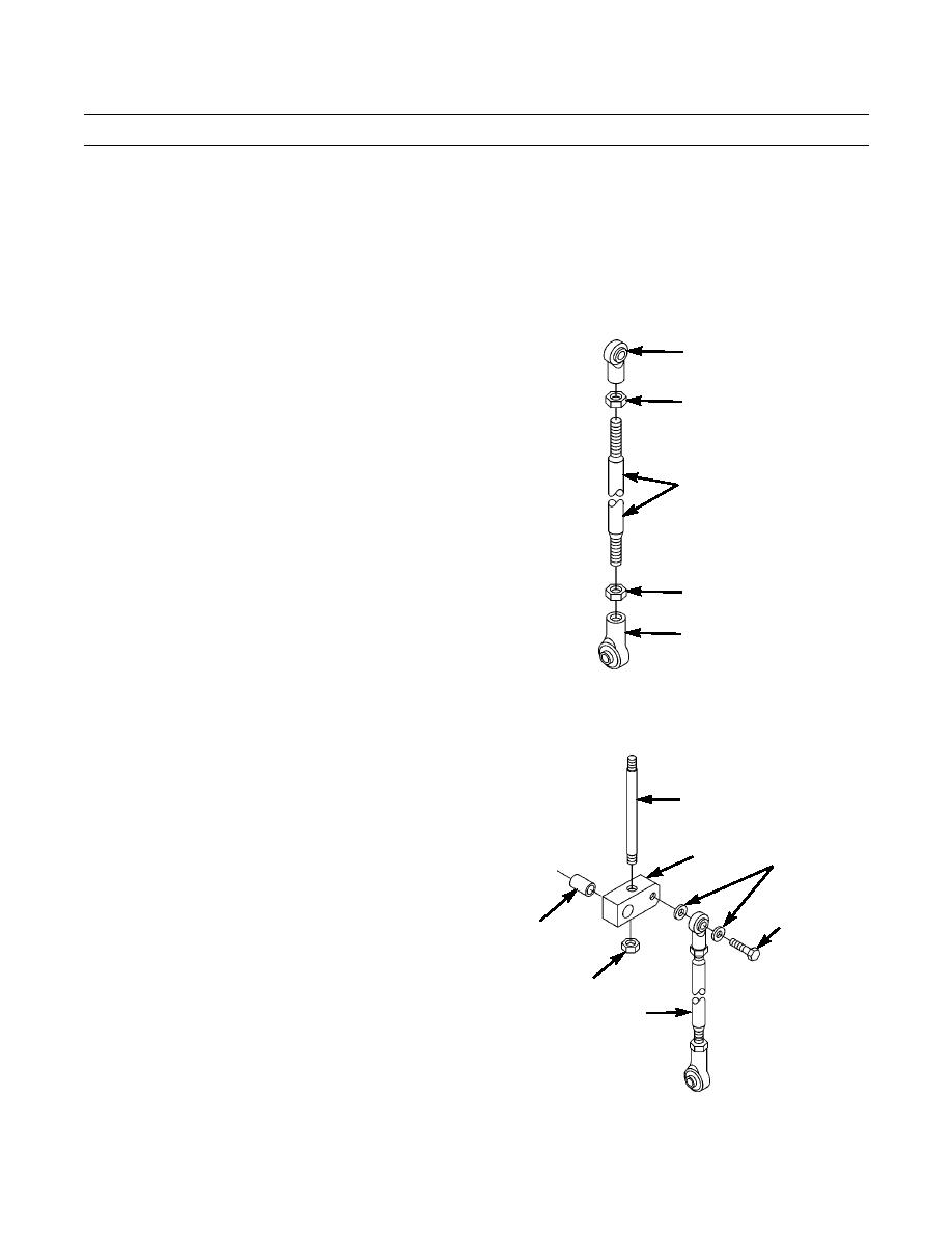
Do not tighten nuts until adjustment is made to rod lengths.
9.
Install two nuts (44) and rod ends (43) on rod (40).
43
44
40
44
43
394-1071
10.
Install two washers (38), rod (40) assembly, and bolt
(39) on connecting link (35).
11.
Install bearing (42) in connecting link (35).
37
12.
Install rod (37) and nut (41).
35
38
39
42
41
40
394-1070
0325 00-10

