
TM 5-3805-248-23-2
SUPPLEMENTAL STEERING PUMP REPAIR - CONTINUED
0379 00
DISASSEMBLY - CONTINUED
49.
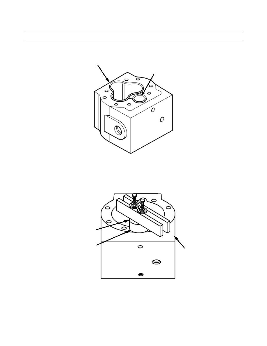
Position valve body (4) assembly in soft-jawed vise with retainer (80) facing upward.
4
80 (HIDDEN)
394-1530
50.
Use a 3/8-16NC tap to tap two holes opposite each other in the retainer (80).
51.
Position a 1.375 in. (3.49 cm) ID spacer over the center of retainer (80). Spacer is to have a height of 1 in. (2.54 cm) and
an outer diameter large enough to position on the machined surface of valve body (4).
52.
Install two 3/8-16NC x 3-1/2 forcing screws, 3/8-16NC nuts, 3/8 in. washers and block. Install nut and washer on each
forcing screw. Install one forcing screw through the center and another screw in one of the slots in block. Align and
install forcing screws in each tapped hole of retainer (80).
SPACER
80 (HIDDEN)
4
394-1531
0379 00-9

