TM 5-3805-280-24
FUEL INJECTION LINES
Fuel from the fuel injection pump is sent through
the fuel injection lines to the fuel injection
no77les.
Each fuel injection line of an engine has a special
design and must be inT stilled in a certain
location. _n fuel injection Iines are removed
from an engine, put identification marks or
tags on the fuel lines as they are removed,
so they can be put in the correct location
when they are installed.
The nuts that hold a fuel injection line to an
injection nozzle and injection pump must be
kept tight. Use a torque wrench and the
5P144 Fuel Iine Socket to tighten the fuel line
nuts to 30 + 5 lb. ft. (40 + 7 Nhm).
FUEL INJECTION PUMPS
When injection pumps, sleeves and lifters are
removed from the injection pump housing, keep the
parts of each pump together so they can be in-
stalled back in their original location.
Be careful when disassembling injection pumps. Do
not damage the surface on the plunger. The
plunger, sleeve and barrel for each pump are made
as a set. Do not put the plunger of one pump in the
barrel or sleeve of another pump. If one part is
sworn, install a complete new pump assembly. Be
careful when putting the plunger in the bore of the
barrel or sleeve.
When an injection pump is installed correctly, the
plunger is through the sleeve and the adjustment
lever is engaged with the groove on the sleeve. The
bushing that holds the injection pump in the pump
housing must be kept tight. Tighten the bushing to
60 + 5 lb. ft. (80 + 7 N.m). Damage to the housing
will result if the bushing it too tight. If the bushing is
not tight enough, the pump *will leak.
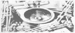
AIR INLET PIPE
(Typical Example)
CAUTION
If the sleeves on one or more of the fuel
injection pumps have been installed wrong,
damage to the engine is possible if cautions
are not taken at first starting. When the fuel
injection pumps have been removed and in-
stalled with the fuel injection pump housing
on engine, take the following cautions when
first starting the engine.
a. Remove air cleaner leaving the air inlet pipe
open as shown.
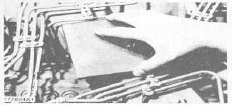
b. If the sleeve on a pump has been installed
*wrong and the engine starts to run too fast,
put a steel plate over the air inlet opening as
show n to stop the engine.
STOPPING THE ENGINE
(Typical Example)
FINDING TOP CENTER COMPRESSION
POSITION FOR NO. 1 PISTON
No. 1 piston at top center (TDC) on the
compression stroke is the starting point for all
timing procedures.
1. Remove the plug from the timing hole (2) in the
front cover. Put bolt (I) in timing hole (2). The bolt
from hole (3) can be used.
2. Turn the crankshaft COUNTERCLOCK-WISE (as
seen from rear of engine) until bolt (I) will go into the
hole in the drive gear for the camshaft.
3. Remove the valve cover on the right side of the
engine (as seen from rear of engine). The two valves
at the right front of the engine are the intake and
exhaust Valves for No. I cylinder.
2-48