TM 5-3805-260-24
reading must be (0.000 + 0.010 mm) as shown.
When the pump calibration is correct make a
record and then do the same procedure for all the other
pumps.
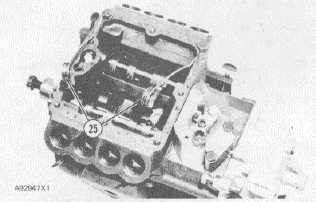
NOTE: When calibrating pumps on the "slave" side [side
opposite from governor control lever (16)], put clamp
(25) on both ends of the sleeve shaft as shown in picture
number A92947X1.
INSTALLING CLAMP ON "SLAVE" SIDE
25. 6V190 Clamps.
GOVERNOR ADJUSTMENTS
CAUTION
A mechanic that has the correct training is the
only one to make the adjustment of low idle
and high idle rpm. The correct low idle and
high idle rpm, and the measurements for
adjustment of fuel setting are given in the
RACK SETTING INFORMATION.
Check engine rpm with a tachometer that has good
accuracy. If the low idle or high idle rpm needs an
adjustment, use the following procedure:
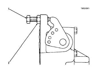
ADJUSTMENT OF LOW IDLE RPM
1. Adjustment boll for low idle. 2. Locknut.
1.
For adjustment of loss idle, loosen lock nut
(2) and turn adjustment bolt (1) to get as
near as possible to the correct low idle rpm.
2. After the low idle adjustment is correct,
tighten locknut (2).
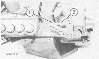
ADJUSTMENT OF LOW IDLE RPM
1. Adjustment bolt for low idle. 2. Locknut.
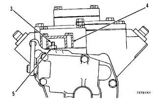
3.
To make an adjustment to the high idle
rpm, remove the small cover (4) at the top
rear of the fuel system.
4.
Loosen locknut (5) and turn adjustment
screw (3) to get as near as possible to the
correct high idle r m.
ADJUSTMENT OF HIGH IDLE RPM
3. Adjustment screw. 4. Cover. 5 Locknut.
5.
After each idle adjustment is made, move,
the governor lever to change the rpm of the
engine. Now move the governor lever back
to the point of first adjustment to check the
idle
adjustment.
Keep
doing
the
adjustment procedure until the low idle and
high idle rpm are the same as given in the
RACK SETTING INFORMATION.
6.
After adjustment of high idle rpm is correct,
tighten locknut (5) and install cover (4).
2-63