TM 5-3805-260-24
DIFFERENTIAL AND BEVEL GEAR
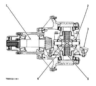
DIFFERENTIAL
1. Pinion shaft. 2. Pinions (four). 3. Bevel
gear.
4. Spider. 5. Side gears (two).
The gear on the transmission output shaft is engaged
with the transfer output shaft gear which sends power
through universal joints to the drive shafts. The drive
shafts are connected with splines to the pinion shaft (1).
The pinion shaft turns the bevel gear (3) which is
fastened to the differential case. The differential case
contains four pinions (2), installed on a spider (4), and
two side gears (5). The four pinions are engaged at right
angles with the two side gears. The side gears are
connected with splines to the inner ends of the drive
axles.
The differential makes the torque equal that goes to
both drive wheels. When one wheel is turning slower
than the other, as in a turn, the differential permits the
inside wheel to stop or slow in relation to the outside
wheel.
When the machine is moving straight ahead with
equal traction under each drive wheel, equal torque on
each axle stops the pinions (2) so they will not turn on
the spider (4). This gives the same action as if both
drive wheels were locked on the same driving axle.
When loads that are not equal are put on the drive
wheels, as in a turn, forces that are not equal are put on
opposite sides of the differential causing the pinions (2)
to turn. When the pinions are turning, the inside wheel
slows or stops and increases the turning of the outside
wheel. This action causes the machine to be driven with
full power in a turn.
The hubs of the differential cases are installed on the
differential carrier with tapered roller bearings. The
pinions (2) turn on hardened steel bearings. Both the
pinions (2) and side gears (5) turn against thrust washers
which take the end thrust against the differential case.
The differential gets lubrication from oil thrown about
by the moving parts. Flat surfaces on the spider permit
passage of oil for lubrication to the pinion bearings and
the thrust washers.
2-96