TM 5-3805-260-24
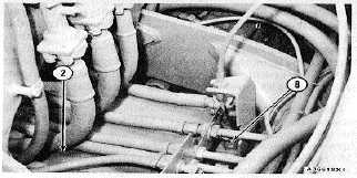
ELEVATOR SPEED VALVE
2. Transmission. 8. Valve spool (in LOW SPEED
position).
The elevator speed valve is beside transmission (2) on
the right side of the machine. The flexible cable from the
elevator speed lever is connected to valve spool (8) in
the speed control valve.
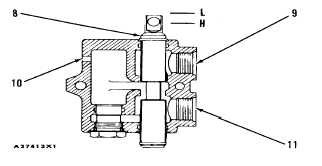
ELEVATOR SPEED VALVE
8. Valve spool. 9. Outlet (to the tank). 10. Inlet from
pump. 11. Outlet (to hydraulic motor). H. HIGH
SPEED position. L. LOW SPEED position.
Hydraulic elevator motor
Oil from the pump goes through inlet (10) and
through outlet (9) to the tank when valve spool (8) is in
LOW SPEED position (L). When the elevator speed
lever is moved to the HI position as shown, the flexible
cable moves valve spool (8) to HIGH SPEED position
(H). Now, the pump oil through inlet (10) goes through
outlet (11) and to an oil line from the other pump section.
The oil from both pump sections goes to the elevator
motor and runs the elevator at high rpm.
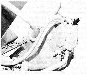
SCRAPER VALVES
Control Valve (Lift Circuit)
The scraper control valve is beside the transmission
near the right side of the machine.
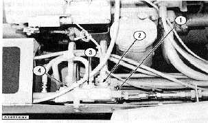
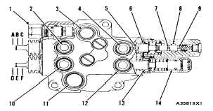
SCRAPER CONTROL VALVE
1. Relief valve. 2. Line (to head ends of bowl
cylinders. 3. Inlet (pump). 4. Line (to rod ends of
bowl cylinders).
SCRAPER CONTROL VALVE
1. Relief valve. 2. Opening (to head ends of bowl
cylinders). 3. Inlet (from pump). 4. Opening (to rod
ends of bowl cylinders). 5. Hole (to passage in valve
stem). 6. Bowl valve spool. 7. Hole (to passage In
valve stem). 8. Passage (from vent line for carry
check valves). 9. Hole (to passage In valve stem). 10.
Opening (to ejector and door cylinder). 11. Outlet (to
tank). 12. Opening (to ejector and door cylinder). 13.
Ejector valve spool. 14. Ejector kick-out valve. A. UP
position. B.HOLD position. C. DOWN position. D.
EJECT (Open) position. E. HOLD position. F.
RETURN (Close) position.
4-21