TM 5-3805-260-24
ELECTICAL SYSTEM
The electrical system has three separate circuits:
the charging circuit, the starting circuit and the low
amperage circuit. Some of the electrical system
components are used in more than one circuit. The
battery (batteries), circuit breaker, ammeter, cables and
wires from the battery are all common in each of the
circuits.
The charging circuit is in operation when the
engine is running. An alternator makes electricity for the
charging circuit. A voltage regulator in the circuit controls
the electrical output to keep the battery at full charge.
The starting circuit is in operation only when the start
switch is activated.
The low amperage circuit and the charging
circuit are both connected to the same side of the
ammeter. The starting circuit connects to the opposite
side of the ammeter.
SYSTEM COMPONENTS
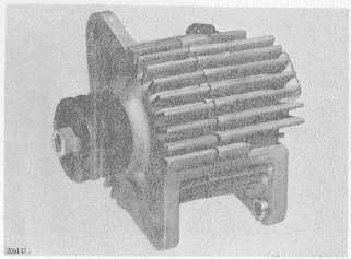
Alternator (Prestolite) 2P1204
The alternator is driven by V type belts from the
crankshaft pulley. It is a 24 volt, 19 ampere unit with a
regulator which has no moving parts (solid state)
installed on the side opposite the pulley. The alternator
is made up of the following parts: head assembly on the
drive end, rotor assembly, stator assembly, rectifier and
heat removal assemblies, brush and holder assembly,
head assembly on the ring end, and regulator.
The alternator has diodes which change the
alternating current (AC) made by the alternator to direct
current (DC). This direct current is used to make
magnet like lines of force in a space around the stator
assembly (field current). The field current is controlled
by the regulator.
Alternator (Delco-Remy)
The alternator is a three phase, self rectifying
charging unit. The regulator for the alternator is part of
the alternator. The alternator is driven from the
crankshaft pulley by two V type belts.
The only part in the alternator which has
movement is the rotor. The rotor is held in position by a
ball bearing at the drive end and a roller bearing at the
rectifier end.
The compartment for the regulator is sealed.
The regulator controls the alternator output according to
the needs of the battery and the other components in the
electrical system.
Starting Motor
The starting motor is used to turn the engine
flywheel fast enough to get the engine running.
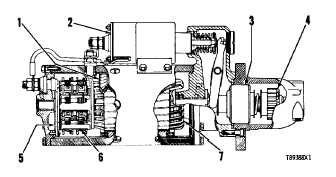
STARTING MOTOR
1. Field. 2. Solenoid. 3. Clutch. 4. Pinion.
5. Commutator. 6. Brush assembly. 7.
Armature.
The starting motor has a solenoid. When the
start switch is activated, electricity from the electrical
system will cause the solenoid to move the starter pinion
to engage with the ring gear on the flywheel of the
engine. The starter pinion will engage with the ring gear
before the electric contacts in the solenoid close the
circuit between the battery and the starting motor. When
the start switch is released, the starter pinion will move
away from the ring gear of the flywheel.
2-19