
TM 5-3805-248-23-1
DIFFERENTIAL LOCK CONTROL VALVE ASSEMBLY MAINTENANCE - CONTINUED
0173 00
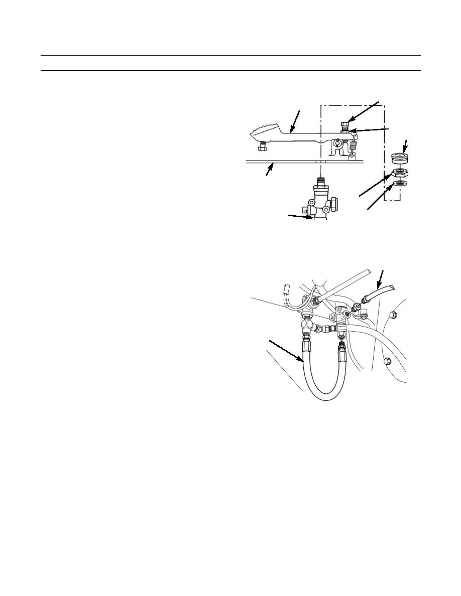
INSTALLATION
1.
With assistance, insert differential lock control valve
4
3
assembly through hole in floor from under left side of
cab.
2.
Install washer (7), nut (8) and boot (6) on differential
5
6
lock control valve.
CAB FLOOR
8
DIFFERENTIAL
7
LOCK CONTROL
VALVE ASSEMBLY
394-912
3.
Apply sealing compound to threads of hose assembly
1
(2) and tube assembly (1) and install on differential
lock control valve.
2
394-911
0173 00-6

