TM 5-2350-262-20-3
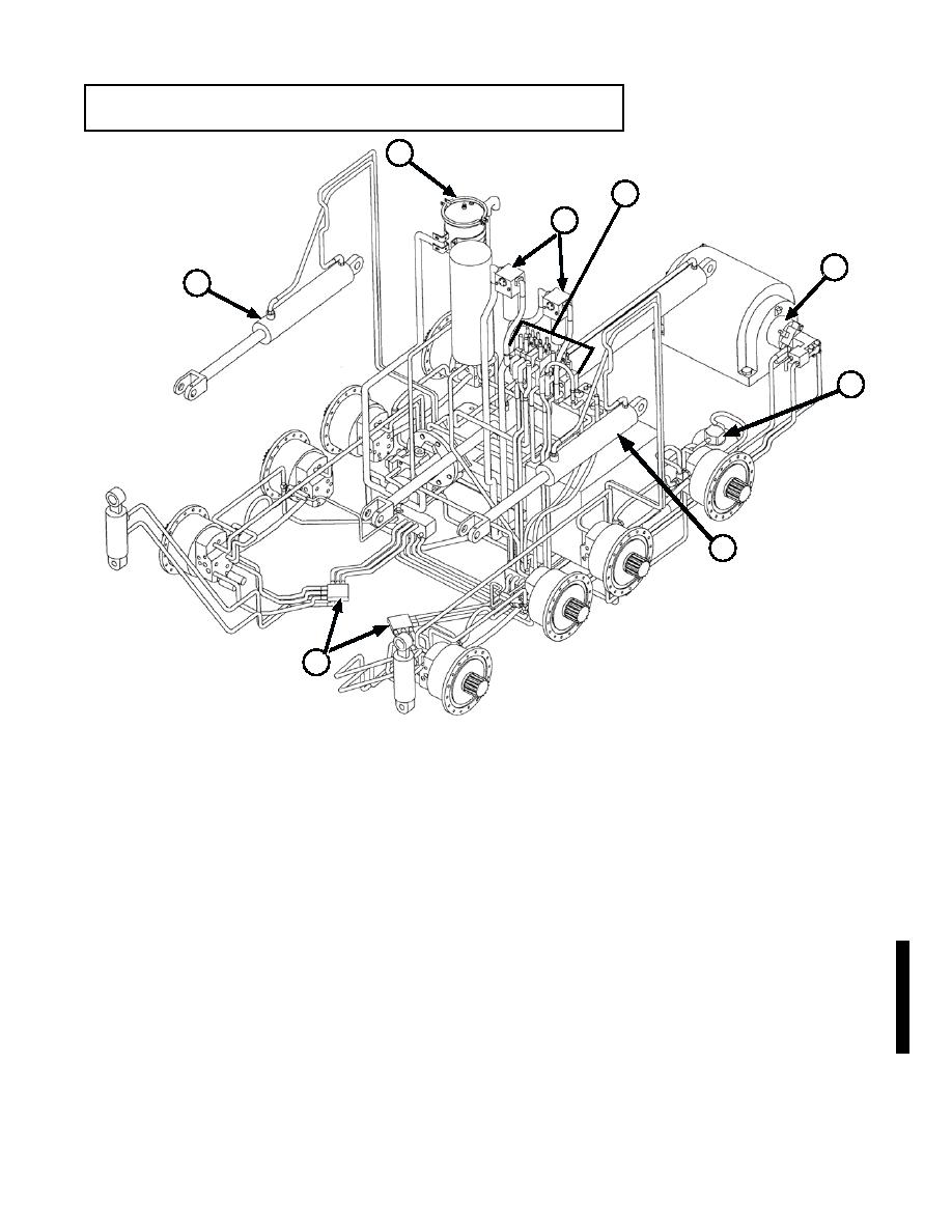
LOCATION AND DESCRIPTION OF MAJOR COMPONENTS
2
4
3
5
1
6
1
7
(1)
APRON CYLINDER. Raises and lowers apron and dozer assembly (one each side).
(2)
RETURN LINE FILTER. Filters out contaminants from hydraulic oil that is returning to reservoir.
(3)
HIGH PRESSURE FILTERS. Two high-pressure filters located directly in front of driver's
compartment filter hydraulic fluid from the main hydraulic pump while it is enroute to the directional
control valve bank.
(4)
DIRECTIONAL CONTROL VALVE. Activated by mechanical linkages from the operator's controls
to activate hydraulic functions in the vehicle. Controls direction of fluid flow and pressure.
(5)
WINCH MOTOR. Operates the winch which is used in recovery operations.
NOTE
Although the Bilge Pump is considered Not Mission Essential and will no longer be
supported with spare and repair parts, this manual contains troubleshooting procedures
For Your Information Only. See TB 43 0001-62-7 (dated Oct 98) for Instructions to
Isolate and Disconnect a Non-functional Bilge Pump.
(6)
BILGE PUMP MOTOR. Starts bilge pump operation through hydraulic pressure when bilge pump
control lever is activated.
(7)
FORWARD MANIFOLD. Routes the flow of hydraulic fluid to components.
Change 2


