TM 5-3800-205-24-1
BLACKOUT DRIVE LIGHT MAINTENANCE - CONTINUED
0052 00
LIGHT ASSEMBLY REMOVAL - CONTINUED
4.
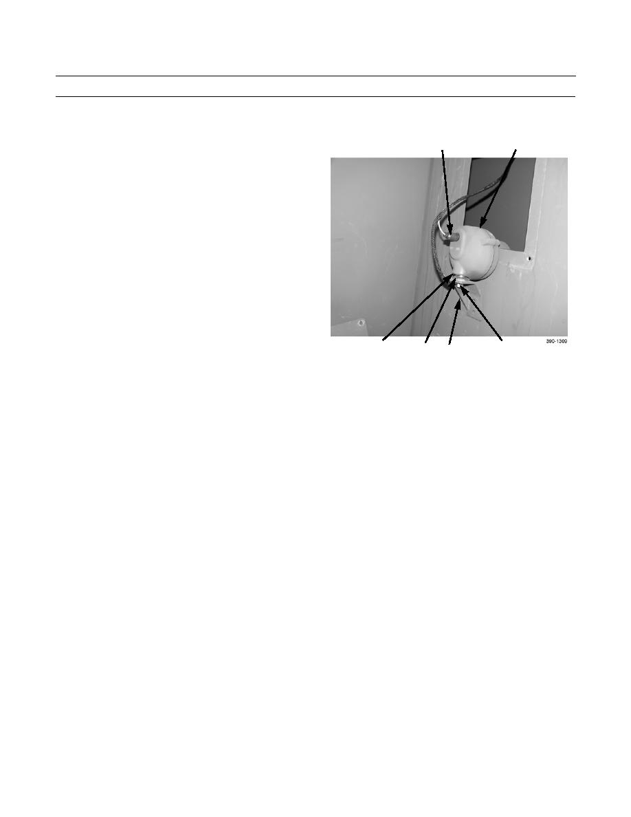
Disconnect electrical lead (15) from light assembly
10
15
(10).
5.
Remove nut (16), lockwasher (17), and ground lead
(18) from stud (19).
6.
Remove light assembly (10), swivel (20), and spacer
(21) from mounting bracket (11).
21
16,17,18,19
20
11
LIGHT ASSEMBLY INSTALLATION
1.
Install light assembly (10), swivel (20), and spacer (21) on mounting bracket (11).
2.
Install ground lead (18) on stud (19) with lockwasher (17) and nut (16).
3.
Connect electrical lead (15) to light assembly (10).
4.
Position light assembly (10), through access plate opening.
5.
Install two screws (12), four washers (13), and two nuts (14) on mounting bracket (11).
6.
Install access plate (9) with four washers (8) and screws (7).
END OF WORK PACKAGE
0052 00-4


