TM 5-3805-248-23-1
DIFFERENTIAL LOCK CONTROL VALVE ASSEMBLY MAINTENANCE - CONTINUED
0173 00
REMOVAL - CONTINUED
4
3
3.
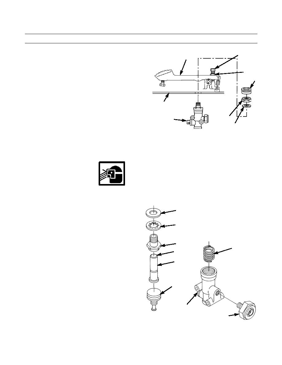
Loosen nut (5) and bolt (4) and raise pedal assembly
(3).
5
4.
Support differential lock control valve assembly and
6
remove boot (6), nut (8) and washer (7) from differen-
tial lock control valve.
5.
With assistance, remove differential lock control valve
assembly from cab floor.
CAB FLOOR
8
DIFFERENTIAL
LOCK CONTROL
7
VALVE ASSEMBLY
394-912
DISASSEMBLY
1.
Remove washers (9 and 10) from sleeve (11).
2.
Remove connector (14) and valve (13) from differential lock control valve.
WARNING
Some components are under spring tension. Wear eye protection and use caution during disassembly to
avoid injury.
3.
Remove sleeve (11), plunger assembly (16), spool
9
assembly (17) and spring (12) from differential lock
control valve.
10
11
12
15
16
17
14
13
394-913
0173 00-2


