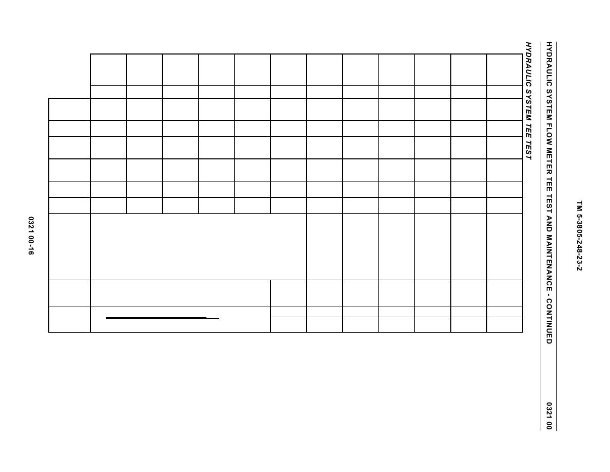
Table 1. Hydraulic System Tee Test.
Maximum
System Oil
Pressure
Temp-
Ejector
System Oil
Bowl Circuit
Apron
Relief Valve
erature
System Base
Forward
Bowl Raise
Bowl Raise
Bowl Lower
Apron Up
Apron Down
Temperature
Drift
Circuit Drift
Setting
(Start)
Flow Rate
Flow rate
Flow Rate
Flow Rate
Flow Rate
Flow Rate
Flow Rate
(End)
Compare
Compare
1
2
3
4
5
6
7
8
9
10
11
12
Apron
Ejector
Bowl Hold
Apron Hold
Control Lever
Ejector
Ejector
Ejector
Ejector
Apron Up
Bowl Raise
Bowl Raise
Bowl Lower
Raise
Position
Forward
Forward
Forward
Return
Down
Forward
Raise
Engine Speed in
1,900
Any Speed
1,900
1,900
1,900
1,900
1,900
1,900
1,900
Any Speed
Low Idle
Low Idle
RPM
System Test
Maximum
0-100
100 (689)
1,000 (6,895)
1,000 (6,895)
1,000 (6,895)
1,000 (6,895)
1,000 (6,895)
1,000 (6,895)
0-100 (0-689)
0
0
Pressure - psi
(0-689)
(kPa)
Test Data
2,100-2,200
145-155F
79 gpm
67 gpm
67 gpm
67 gpm
63 gpm (239 l/
67 gpm
67 gpm
145-155F
Hold M S
Hold M S
psi (14,479-
(63-68C)
(300 l/min)
(254 l/min)
(254 l/min)
(254 l/min)
min)
(254 l/min)
(254 l/min)
(63-68C)
15,168 kPa)
Flow
12 gpm
12 gpm
12 gpm
16 gpm
12 gpm
12 gpm
Raise M S
Raise M S
Differential
(45 l/min)
(45 l/min)
(45 l/min)
(61 l/min)
(45 l/min)
(45 l/min)
Percent Flow
15%
15%
15%
20%
15%
15%
Loss
Finish oil temperature, Test 10 must be within ten percent 15F (-9C) of start oil
System Oil
Temperature:
temperature, Test 2.
For each 15 degrees that the finish is higher than the start, Test 10 greater than Test 2,
subtract 0.5 gal. from the leakage rate.
For each 15 degrees that the finish is lower than the start, Test 2 greater than Test 10,
add 0.5 gal. to the leakage rate.
Flow Differen-
tial Calcula-
tion
System Base Flow Rate - Test Flow Rate
(System Base Flow Rate - Test Flow Rate)
X 100
Percent Flow
System Base Flow Rate
Loss


