TM 5-3805-260-24
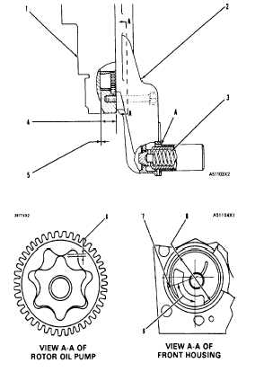
OIL PUMP
(A)
Position of guide
Even with finished surface on cover to not more than 010 (0 25
mm) recessed
NOTE Make sure the flat surface on the guide is in alignment with
the set screw
(1)
Front housing assembly.
(2)
Oil pump cover assembly
(3)
9L9243 Spring (pump pressure relief valve)
Length under test force....... ............2 579 in (65 51 mm)
Test force............... ............ ............37 31 9 lb (166.5 8 5 N)
Free length after test .......... ...........3 50 in (88 9 mm)
Outside diameter ... ............ ............875 in (22 23 mm)
(4)
Width of oil pump rotors
(new)...................... ............1 2480 + 0003 in (31 699 +- 0008 mm)
Depth of counterbore in front
housing (new) .......1.252 001 in (31 80 + 0 03 mm)
(5)
Maximum permissible end clearance of oil pump
rotors when measured with oil pump installed to
front cover ............. ............ ............006 in (0 15 mm)
(6)
Clearance of oil pump
rotor tip .................. ............ ............002 to 006 in (0.05 to 0.15 mm)
Maximum permissible clearance of oil pump
rotor tip................... ............ ............009 in ( 23 mm)
(7)
Bearing junction
(8)
Diameter of bearing for
rotor (new) ............. ............ ............2.8041 0022 in (71.224
0.056 mm)
(9)
Position of main bearing junction from vertical
centerline ............... ............ ............75 30
1-19