
TM 5-3805-248-23-2
CYLINDER BLOCK REPAIR - CONTINUED
0342 00
ASSEMBLY - CONTINUED
CAUTION
Liner projection for all six liners must be measured and recorded before removing and replacing liners to
meet projection specifications. This requirement applies when one or more counterbores are cut. Failure to
follow this procedure could result in damage to equipment.
NOTE
Counterbore depth, insert thickness and liner height may vary. In order to achieve uniform liner projection
(height), liners can be placed in different cylinder bores until the correct placement is determined. In addi-
tion, rotating the liner in the bore may result in more uniform projection.
4.
Compare measurements recorded in Inspection, step 15 with projection specifications. All six cylinder liners must
project from 0.002 to 0.006 in. (0.0508 to 0.1524 mm) from spacer plate (40). If not, return to step 28.
5.
Determine average projection for each of the six cylinder liners (39) by adding together the four measurements recorded
in Inspection, step 15, and dividing by 4.
6.
Determine average projection for all side-by-side cylinder lines (39) by subtracting smaller average from larger average.
If average side-by-side liner projection difference is 0.001 in. (0.0254 mm) or less, proceed to step 13. If difference is
more than 0.001 in. (0.0254 mm), complete steps 7 through 14.
CAUTION
Liner projection specifications in steps 9 through 14 must be met before cylinder block is assembled. To
meet the requirements, cylinder liners and counterbore inserts can be interchanged, as long as previous mea-
surement criteria are within specifications. Failure to follow this procedure could result in damage to equip-
ment.
7.
Remove liner projection tool group. Refer to Inspection, steps 16 through 18.
8.
Remove cylinder liners (39) with highest and lowest
projections from cylinder block.
39
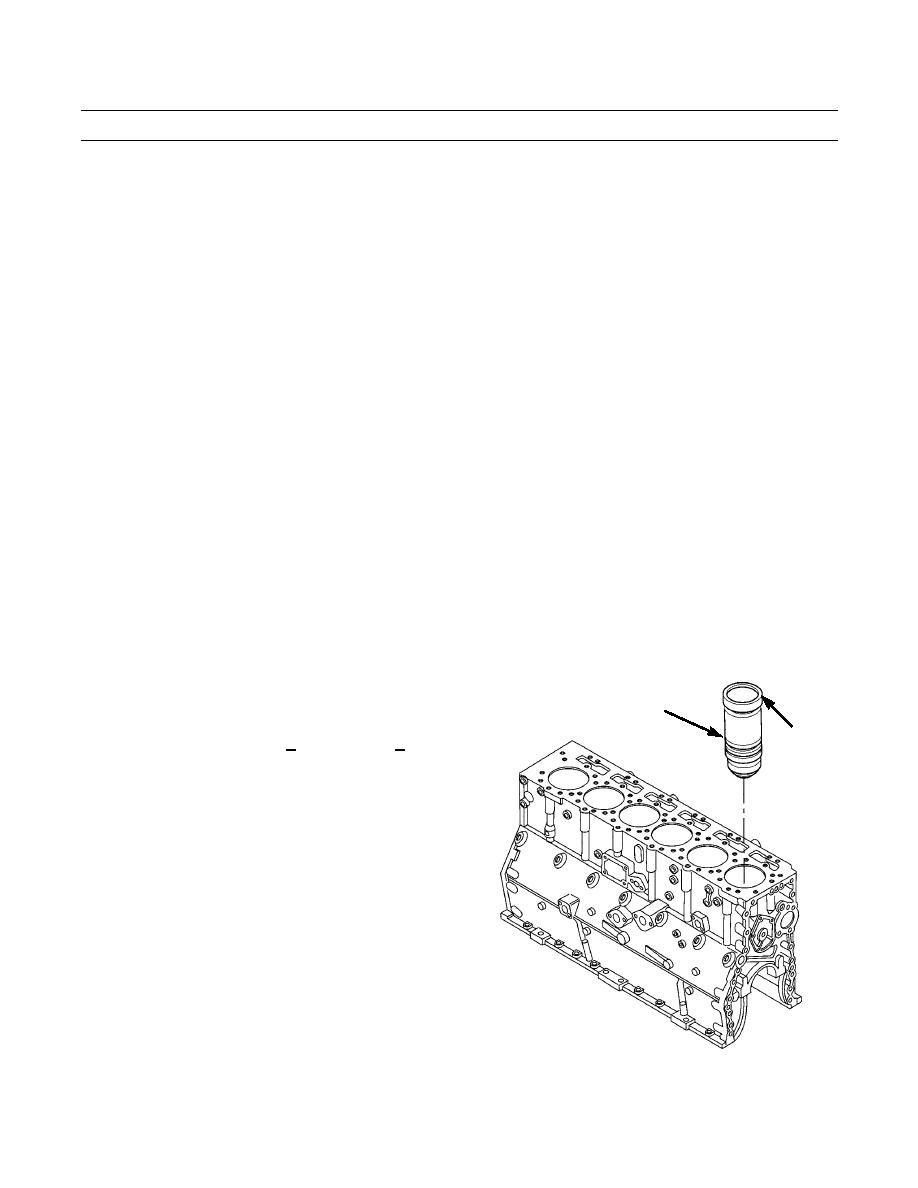
9.
Measure flange thickness of cylinder liners (39).
FLANGE
Thickness must be 0.350+0.008 in. (8.89+0.2032
mm).
10.
Install cylinder liners (39) in positions where projec-
tion heights are within specifications.
11.
Remove counterbore inserts from counterbore.
394-1113
0342 00-11

