TM 5-2350-262-20-3
2
APRON, BILGE PUMP, AND LEFT-HAND WHEEL CONTROL INOPERATIVE
The inboard valve bank hydraulic system 13R circuit is supplied by hydraulic pump port 13R and pressure
is controlled by the relief valve at inlet port 13R.
NOTE
Perform this procedure only when the bilge pump, apron, left-hand suspension
controls, and ejector are all inoperative.
Although the Bilge Pump is considered Not Mission Essential and will no longer be
supported with spare and repair parts, this task contains troubleshooting procedures
For Your Information Only. See TB 43 0001-62-7 (dated Oct 98) for Instructions to Isolate
and Disconnect a Non-functional Bilge Pump.
WARNING
High pressure is present in the M9 hydraulic system. Do not disconnect any hydraulic
system component unless hydraulic system pressure has been relieved. Ensure each
hydraulic control lever is moved several times through all positions and hydraulic tank
dipstick is slowly loosened to relieve pressure. Failure to comply may result in severe
injury or death to personnel.
HIGH-PRESSURE
3
2
CIRCUIT
4
RETURN
SUPPLY
1
1
10
5
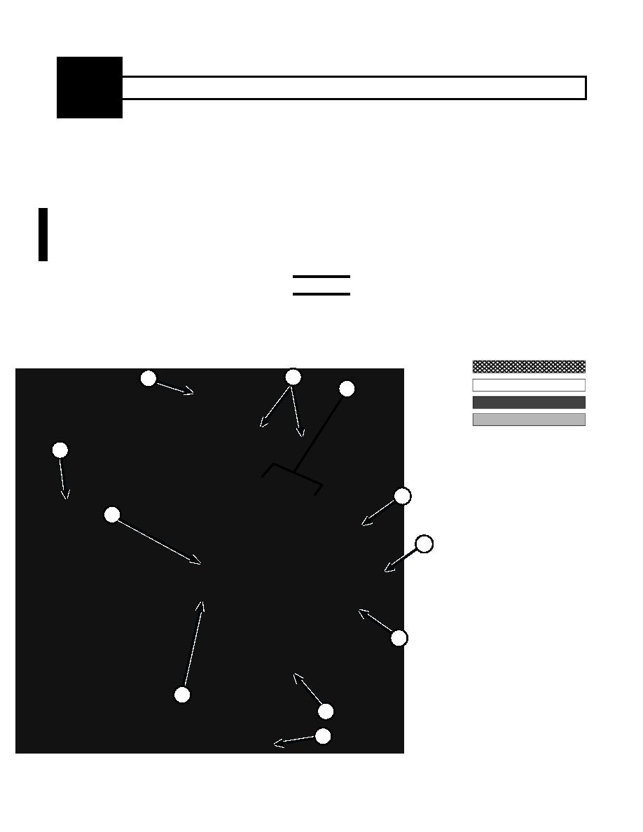
COMPONENTS:
1. APRON CYLINDERS
2. RETURN LINE FILTER
3. HIGH-PRESSURE FILTERS
4. DIRECTIONAL CONTROL
VALVE BANK
6
5. BILGE PUMP
6. HYDRAULIC RESERVOIR
7. MAIN HYDRAULIC MANIFOLD,
RIGHT HAND
9
8. NO. 1 ACTUATOR,LEFT HAND
7
9. EJECTOR CYLINDER
10. MAIN HYDRAULIC PUMP
8
APRON, BILGE PUMP, AND LEFT-HAND WHEEL CONTROL CIRCUIT
Change 2


