TM 5-3800-205-23-1
TRANSMISSION SHIFT CONTROL CAM AND LINKAGE REPLACEMENT - CONTINUED
0070 00
INSTALLATION - CONTINUED
11.
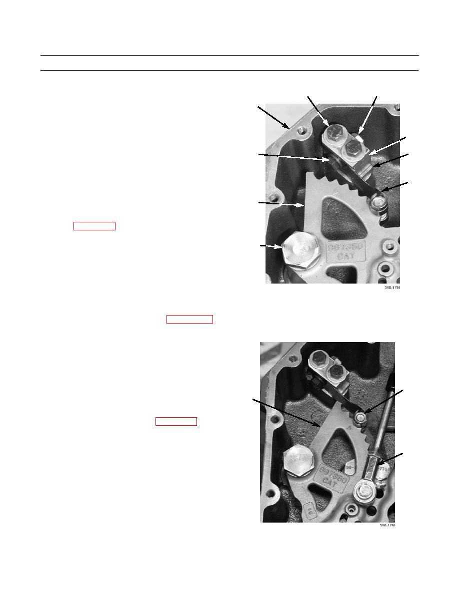
Position cam (11) to linkage housing (1).
4
2,3
12.
Install cam (11) to linkage housing (1) with cam pivot
1
pin (10), washer (9), and bolt (8).
13.
Install spacer block (6) and block (5) to linkage hous-
ing (1) with two washers (3) and bolts (2).
5
NOTE
12,13
6
Install flat spring assembly and detent
notches in cam in same position as noted
7
during removal.
14.
Install flat spring assembly (7) to block (5) with
11
washer (13), bolt (12), and new locknut (4).
15.
Connect transmission shift control cable to transmis-
sion (WP 0069 00).
8,9,10
ADJUSTMENT
1.
Remove cover from linkage housing (WP 0069 00).
2.
Remove cover from control valve housing (Refer to Removal steps 7 and 8).
3.
In cab, place transmission shift lever in position 4 (TM
5-3800-205-10-1 or TM 5-3800-205-10-2).
NOTE
Cam is marked with a number "4".
7
11
4.
Confirm that flat spring assembly (7) fully engages
detent "4" of cam (11). If not, adjust length of trans-
mission shift control cable (33) (WP 0069 00).
33
0070 00-7


