TM 5-3800-205-23-1
TRANSMISSION SHIFT CONTROL CAM AND LINKAGE REPLACEMENT - CONTINUED
0070 00
INSTALLATION
1.
Coat with oil and install two new O-rings (32) and two new O-rings (31) to linkage housing (1).
NOTE
Two bolts are installed from under linkage housing.
2.
Install linkage housing (1) to control valve housing with four bolts (30).
NOTE
Perform steps 3 through 6 to install each of two rods.
3.
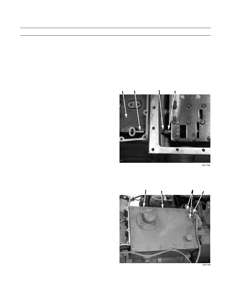
Install new locknut (28) to rod (18).
28
1
29
18
4.
Position rod (18) through linkage housing (1).
NOTE
Install rod and locknut in same position as
noted during removal.
5.
Rotate spool (29) to install spool to rod (18).
6.
While holding spool (29) from rotating, tighten lock-
nut (28).
NOTE
Wiring harness and three cable clamps are also installed as cover is installed.
7.
Install new gasket (24) and cover (23) to top of control
22
25,26
27
23,24
valve housing with 16 bolts (22).
8.
Install lube fitting bracket (27) to cover (23) with two
additional washers (26) and bolts (25).
0070 00-5


