TM 5-3800-205-23-1
TRANSMISSION SHIFT CONTROL CAM AND LINKAGE REPLACEMENT
THIS WORK PACKAGE COVERS
Removal, Installation, Adjustment
INITIAL SETUP
Materials/Parts - Continued
Maintenance Level
Unit
Locknut (3)
Tools and Special Tools
O-ring (4)
Tool kit, general mechanic's (Item 33, WP 0172
Ring, retaining (2)
Materials/Parts
Equipment Condition
Oil, lubricating (Item 24, 27, 28 or 29, WP 0171
Transmission shift control cable disconnected from
transmission (WP 0069 00)
Gasket
REMOVAL
NOTE
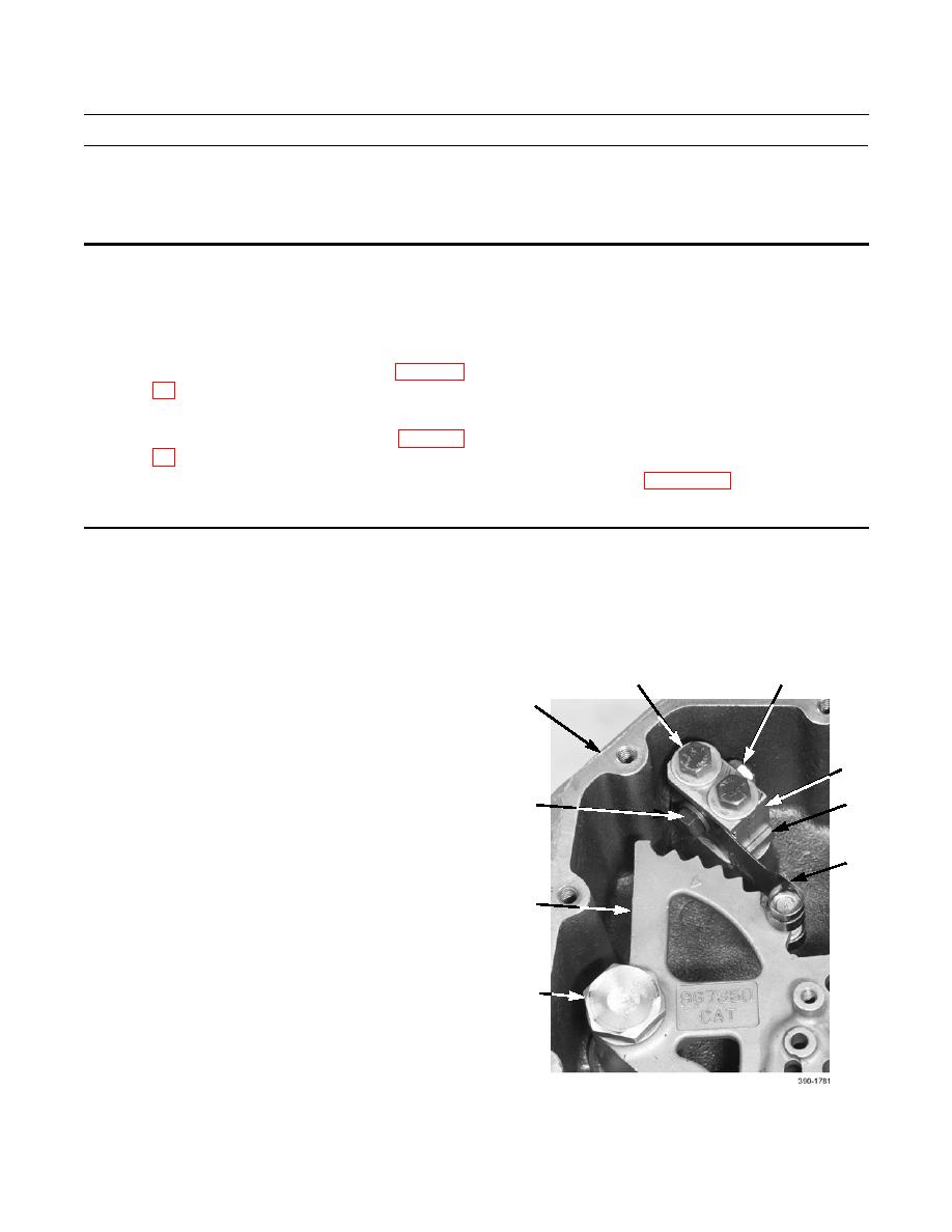
Note position of flat spring assembly and detent notches in cam to aid in installation.
1.
Remove locknut (4), bolt (12), washer (13), and flat
4
2,3
spring assembly (7) from block (5). Discard locknut.
1
2.
Remove two bolts (2), washers (3), block (5), and
spacer block (6) from linkage housing (1).
5
NOTE
Bolt and washer are located underneath
12,13
6
linkage housing.
3.
Remove bolt (8), washer (9), and cam pivot pin (10).
7
NOTE
11
Note position of two levers and channels
of cam as cam is removed.
4.
Remove cam (11) from linkage housing (1).
8,9,10


