TM 5-3800-205-23-1
PARKING BRAKE ASSEMBLY MAINTENANCE - CONTINUED
0082 00
ADJUSTMENT
NOTE
Parking brake is correctly adjusted if machine cannot be moved in second speed forward with engine at
high idle.
Brakedrum must be free to rotate when parking brake is released.
1.
Place battery disconnect swtich in ON position (TM 5-3800-205-10-1 or TM 5-3800-205-10-2).
WARNING
If machine is parked indoors, DO NOT run engine unless exhaust fumes are vented to the outside. Failure to
follow this warning may cause injury or death due to carbon monoxide poisoning.
2.
Start engine (TM 5-3800-205-10-1 or TM 5-3800-205-10-2). Allow air pressure to reach operating pressure.
3.
Move parking brake control knob to OFF position. Stop engine (TM 5-3800-205-10-1 or TM 5-3800-205-10-2).
4.
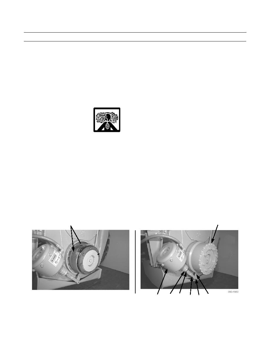
Remove cotter pin (7) and clevis pin (8).
5.
Push end of lever (12) away from parking brake actuator (15) until brake linings (11) come into contact with brakedrum
(3).
6.
Loosen locknut (13). Rotate yoke rod end (9) on threaded rod (14) until holes in yoke rod end and in lever (12) are
aligned. Rotate rod end by one turn toward parking brake actuator (15). Insert clevis pin (8) and cotter pin (7). Tighten
locknut (13).
3
11
13
7,8 12
15
14
9
END OF WORK PACKAGE
0082 00-3


