TM 5-3800-205-23-1
FUEL TRANSFER PUMP AND GOVERNOR ASSEMBLY REPLACEMENT - CONTINUED
0141 00
INSTALLATION - CONTINUED
15.
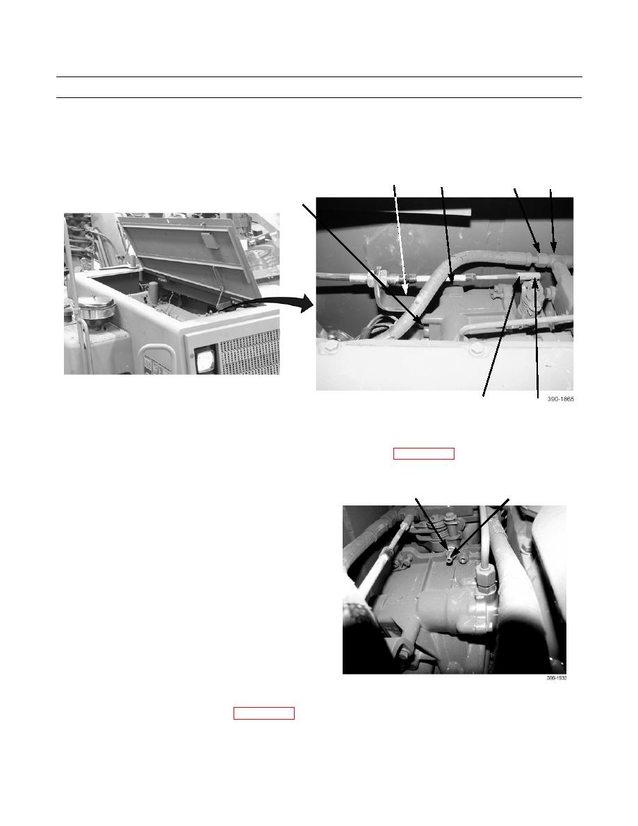
Position cable ball joint (9) on lever and secure with nut (7) and washer (8).
16.
Connect hose (5) to tee (6).
17.
Position bracket (3) on fuel transfer pump/governor (4) and secure with two washers (2) and bolts (1).
3
4
5
6
1,2
9
7,8
(HIDDEN)
ADJUSTMENT
1.
Perform fuel setting, fuel timing, and injector synchronization adjustments (WP 0140 00).
2.
Start engine (TM 5-3800-302-10-1 or TM 5-3800-205-10-2).
3.
With engine at idle speed, loosen locknut (31) and
31
32
adjust low idle screw (32) until 825 RPM is indicated
on instrument panel tachometer.
4.
Tighten locknut (31) and recheck low idle setting.
5.
Close engine access door (TM 5-3800-205-10-1 or
TM 5-3800-205-10-2).
6.
Install front and middle guard plates (WP 0100 00).
END OF WORK PACKAGE
0141 00-11


