TM 5-3800-205-23-2
CHECK VALVE AND LIFT CYLINDER REPLACEMENT - CONTINUED
0021 00
CHECK VALVE INSTALLATION - CONTINUED
5.
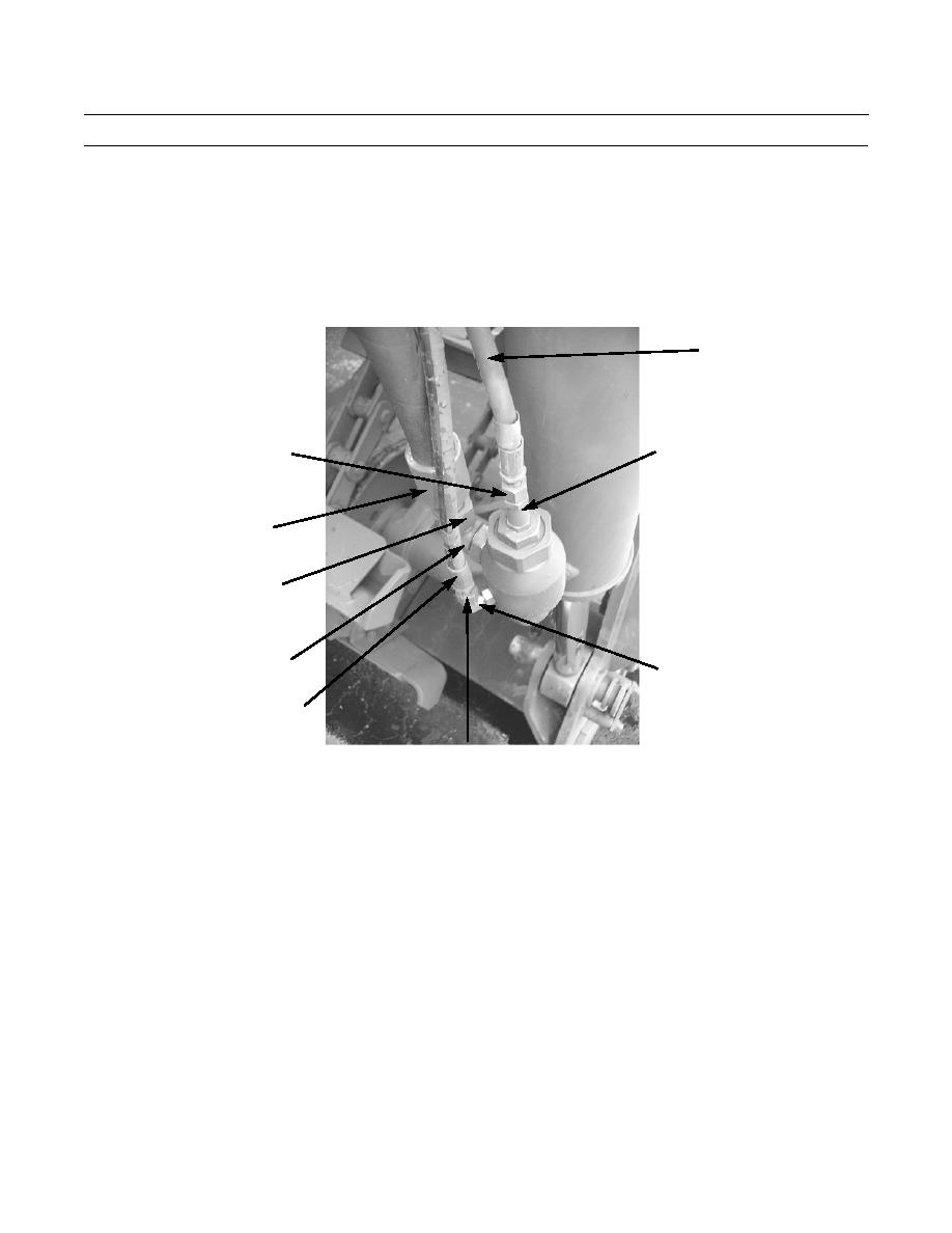
Remove protective cap, connect hose (1) to check valve (2), and tighten nut (9).
6.
Remove protective cap, connect hose (5) to elbow fitting (3), and tighten nut (4).
7.
Remove protective cap, connect hose (8) to swivel adapter (6), and tighten nut (7).
1
2
9
8
7
6
3
5
4
390-1212
8.
Fill hydraulic reservoir with oil (Refer to Unit PMCS in TM 5-3800-205-24-1).
9.
Place battery disconnect switch in ON position (TM 5-3800-205-10-1).
10.
Operate lift cylinders (TM 5-3800-205-10-1) and check for leaks and proper operation.
LIFT CYLINDER REMOVAL
1.
Relieve hydraulic pressure by exercising control levers.
2.
Disconnect three quick disconnect hoses at draft arm (TM 5 3800-205-10-1).
3.
Loosen nut (7) and disconnect hose (8) from swivel adapter (6). Install protective cap.
4.
Loosen nut (4) and disconnect hose (5) from elbow fitting (3). Install protective cap.
5.
Loosen nut (9) and disconnect hose (1) from check valve (2). Install protective cap.
6.
Loosen nut (13) and remove swivel adapter (6) and O-ring (14) from check valve housing (10). Discard O-ring.
7.
Loosen nut (11) and remove elbow fitting (3) and O-ring (12) from check valve housing (10). Discard O-ring.
0021 00-6


