
TM 5-3805-248-23-2
CONTROL LEVER LINKAGE REPLACEMENT - CONTINUED
0325 00
INSTALLATION - CONTINUED
31.
Adjust rod length to equalize side-to-side movement
1
of bowl lever.
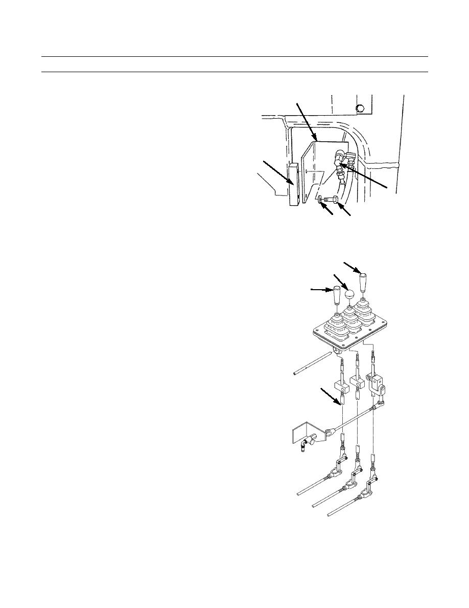
32.
Position apron control valve bracket (1) and apron
control valve (2) assembly on mounting bracket (5).
33.
Install two washers (4) and bolts (3) on mounting
bracket (5).
5
2
391-1054
4
3
ADJUSTMENT
1.
Adjust length of bowl lever vertical rod to 21 in. (53
BOWL LEVER
cm). Rotate clockwise into rod ends to shorten. Rotate
APRON LEVER
counterclockwise to lengthen.
2.
Adjust length of ejector lever vertical rod to 18 in. (46
EJECTOR LEVER
cm). Rotate clockwise into rod ends to shorten. Rotate
counterclockwise to lengthen.
3.
Adjust length of apron lever vertical rod to 15 in. (38
cm). Rotate clockwise into rod ends to shorten. Rotate
counterclockwise to lengthen.
4.
Adjust length of ejector lever horizontal rod to 23 in.
(58 cm). Rotate clockwise into rod end (17) to shorten.
Rotate counterclockwise to lengthen.
5.
Adjust length of apron lever horizontal rod to 26 in.
17
(66 cm). Rotate clockwise into rod end (17) to shorten.
Rotate counterclockwise to lengthen.
6.
Adjust length of bowl lever horizontal rod to 29 in. (74
mm). Rotate clockwise into rod end (17) to shorten.
Rotate counterclockwise to lengthen.
7.
Verify correct operation (TM 5-3805-248-10).
394-1078
END OF WORK PACKAGE
0325 00-14
