
TM 5-3805-248-23-2
CONTROL LEVER LINKAGE REPLACEMENT - CONTINUED
0325 00
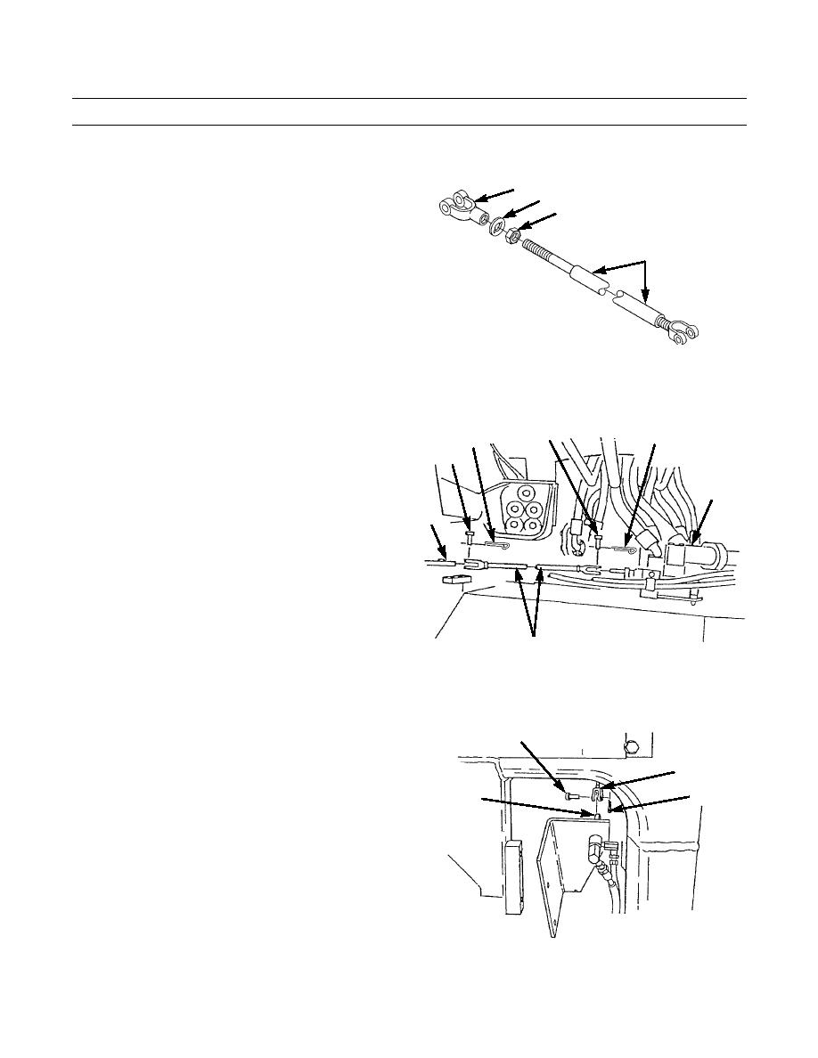
INSTALLATION - CONTINUED
24.
Install nut (19), retainer (18) and clevis (17) on clevis
17
(16).
18
19
16
394-1065
25.
Position clevis end of clevis (16) assembly on lever
13
14
12
(10).
11
26.
Install pin (11) and new cotter pin (12) on clevis (16).
27.
Position rod end of clevis (16) assembly on hydraulic
15
control valve spool (15).
10
28.
Install pin (13) and new cotter pin (14) on clevis (16).
16
394-1064
29.
Position clevis (7) assembly on apron control valve
6
spool (9).
30.
Install pin (6) and new cotter pin (8) on clevis (7).
7
8
9
394-1055
0325 00-13
