TM 5-3805-248-23-2
FUEL INJECTION PUMP REPAIR - CONTINUED
0353 00
ASSEMBLY/ADJUSTMENT - CONTINUED
68.
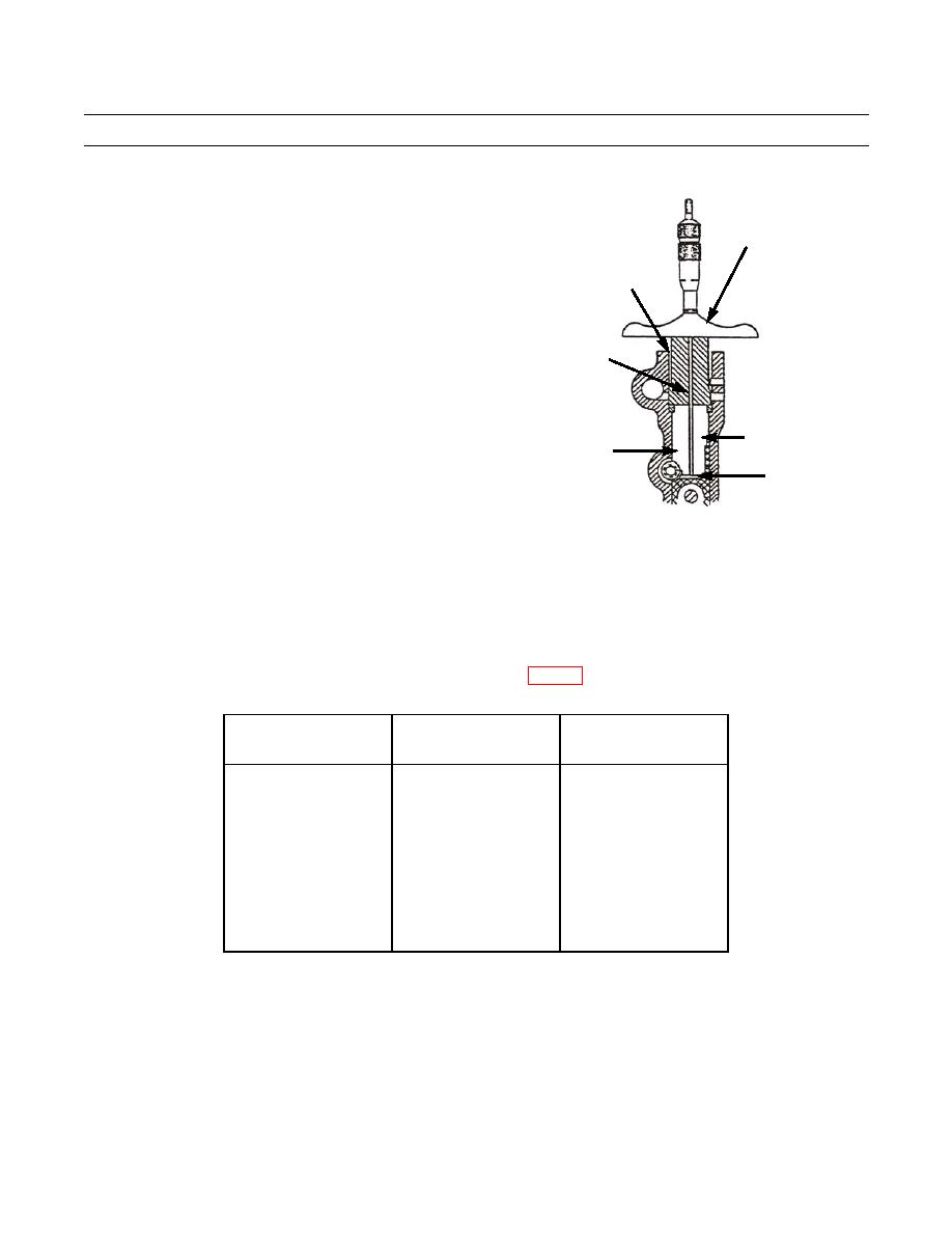
Install new spacer (16) in chamber.
GAGE
4-5 IN. (101.6-127 mm)
ROD
TIMING DIMENSION
INJECTION
PUMP CHAMBER
16
394-1209
69.
Repeat steps 41 through 59. Verify correct timing dimension for all six pump chambers.
NOTE
Steps 69 through 89 are the procedure for installation of the injection pumps in the fuel injection pump hous-
ing. Complete these steps for all six injection pumps before proceeding to step 90.
70.
Rotate timing plate counterclockwise to correct position. Refer to Table 3.
Order of
Timing Plate
Pump Chamber
Installation
Position (in degrees)
Number
1
346.75
1
2
286.75
4
3
266.75
2
4
166.75
6
5
106.75
3
6
46.75
5
0353 00-15


