TM 5-3805-260-24
4.
Connect for a moment, a wire from the solenoid
connection (terminal) "MOTOR" to the ground
connection (terminal). The pinion shift to crank
position and will stay until the battery is
disconnected.
5.
Push the pinion toward commutator end to
remove free movement.
6.
See SPECIFICATIONS for the correct Delco-
Remy pinion clearance.
7.
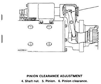
Pinion clearance adjustment is made moving
plug and turning nut (4).
Pinion Clearance Adjustment (Prestolite)
There are two adjustments for this type starting
motors. They are end play for the armature pinion
clearance.
End Play for the Armature
The correct end play for the armature is .005 to .030
in. (0.13 to 0.76 mm). To make an adjustment to the
end play for the armature, add or remove thrust washers
on the commutator end of the armature shaft.
Pinion Clearance
1.
To make an adjustment to the pinion clearance,
connect the solenoid to a 12 volt battery as
shown.
2.
Connect for a short moment, a wire from the
solenoid connection (terminal) "MOTOR” to the
terminal (I) at the commutator end. The solenoid
and drive will shift to the position and will stay
there until the battery is disconnected.
3.
Push the drive toward the commutator remove
any free movement.
4.
Measure the pinion clearance (3). The pinion
clearance (3) must be .020 to .050 in. (0.51 to
1.27 mm).
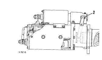
CONNECTIONS FOR ADJUSTMENT OF
THE PINION CLEARANCE
1. Terminal
5.
To make an adjustment to the pinion clearance,
remove the plug and turn the adjustment nut (2) as
necessary.
PINION CLEARANCE ADJUSTMENT
2. Adjustment nut. 3. Pinion clearance.
2-79/(2-180 Blank)