TM 5-3805-260-24
Alternator Regulator (Prestolite)
The
regulator
components
are
sealed
in
an
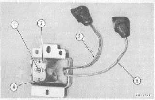
insulation of epoxy. The regulator is an electronic
component with no moving parts (solid state) and an
adjustment screw (1) on the back. This voltage
adjustment screw is used to meet different operating
needs at different times of the year. An increase or
decrease by .5 volts from the normal setting is made by
removing the regulator changing the position of the
adjustment screw washer. An increase to the voltage will
be mad moving the screw and washer to the "H" position
(2).
ALTERNATOR REGULATOR
1. Adjustment screw with washer. 2. High output
position. 3. Orange wire to battery. 4. Low output
position. 5. Green wire to field terminal of the alter-
nator (F).
Alternator Regulator (Delco-Remy)
The voltage adjustment screw for the later alternator
is located under the end plate.
To adjust the voltage setting, use the follow
procedure:
1.
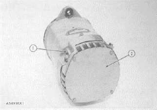
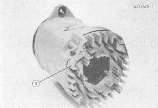
Remove end plate (2) and cover (3) from
alternator.
2.
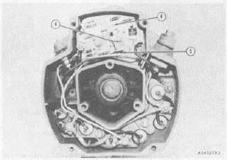
Remove the rubber sealant from the adjustment
screw (4).
ALTERNATOR
1. Adjustment screw under plug (earlier regulator).
2. End plate
LOCATION OF COVER
3. Cover
ALTERNATOR REGULATOR
4. Voltage adjustment screw. 5. Field wire. 6.
Transistor pins
3.
Use a voltmeter to measure alternator volt
output.
4.
Turn adjustment screw (4) counterclockwise to
lower the voltage setting. Turn adjustment
screw (4) clockwise to raise the voltage setting.
2-77


