TM5-3805-260-24
The one-way check valves are used to let air flow in
one direction only. Air, coming into the check valve on
the internal thread end of the valve, will put spring (3) in
compression and valve (2) will open. Air under pressure
is now’ free to flow through the check valve.
Air, coming into the check valve on the external
thread end, will push valve (2) against seat (I). The flow
of air is stopped.
Brake Control Valve
When the brake pedal is pushed, a force is put on
seat (I). This force pushes rubber spring (2) and piston
assembly (3) down. Valve seat (7) closes exhaust
passage (12) in valve (9). Piston assembly (3) moves
valve (9) off of valve seat (8). Pressure air from inlet
passage (13) goes around salve (9) to outlet passage
(6). The air then goes to the relay valve for the scraper
and tractor air chambers.
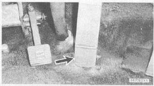
TYPICAL LOCATION OF BRAKE CONTROL VALVE
(Under Pedal)
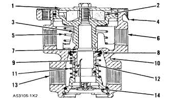
BRAKE CONTROL VALVE
1. Seat. 2. Rubber spring (2). 3. Piston assembly. 4.
Retainer. 5. Spring. 6. Outlet to double check valve.
7. Valve seat. 8. Valve seal. 9. Valve. 10. Valve body.
11. Valve spring. 12. Exhaust passage. 13. Inlet
passage to dry tank. 14. Exhaust diaphragm.
When the air pressure below piston assembly (3)
becomes more than the force above the piston, the
piston lifts enough to let valve (9) move up to valve seat
(8). This stops the supply of pressure air. Piston
assembly (3) is still in contact with valve (9), so exhaust
passage (12) is also closed. The control valve is now in
balance. A pressure is held in the
lines and the air chambers for the wheel brakes.
If the pedal is lifted a small amount, the mechanical
force above piston assembly (3) is less. The pressure
air below the piston and the force of spring (5) will lift the
piston off of valve (9). Pressure air in the lines and the
air chambers goes around piston assembly (3), through
exhaust passage (12) and out exhaust diaphragm (14)
until the forces above and below the piston are in
balance. When the pedal is complete released, piston
assembly (3) moves off valve (9) and releases the air
pressure. valve (9) is held against valve seat (8) by
spring (11).
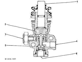
Differential Lock Valve
The differential lock valve controls the supply of air to
the differential lock cylinder and to the control port of the
pilot salve. Depressing the pedal moves plunger (I) and
spool (2) down unseating valve (5) and allows air to flow
from supply port (6) out through delivery port (4) to the
locking piston and the pilot valve. Releasing the pedal
allows the valve return, sealing supply port (6) and
allowing air to flow from the piston and pilot valve out
through exhaust port (3).
DIFFERENTIAL LOCK VALVE
1. Plunger. 2. Spool. 3. Exhaust port. 4. Delivery port.
5. Valve. 6. Supply port.
2-133