TM 5-3805-260-24
CRANKSHAFT
Surface
finish
must
be
10
micro
inches
(0.25
micrometers) or less.
Radius (E) must be .095 .010 in. (2.41 0.25 mm)
Surface finish must be 63 micro inches (1.6
micrometers) or less.
The radius must blend smoothly with the newly
machined journals.
Width (F) is 1.258 .002 in. (31.95 0.05 mm) for
number 4 main bearing journal. Surface finish on the
thrust faces of the number 4 main must be 18 micro
inches (0.45 micrometers) or less. Width (F) is 1.268 +
.020 - .010 in. (32.21 + 0.51 - 0.25 mm) for number 2, 3,
and 5 main bearing journals.
There is no width (F) for number 1 main bearing
journal.
When grinding a crankshaft, no material can be
removed from the crankshaft webs or counterweights.
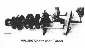
CRANKSHAFT GEAR REMOVAL
Remove the gear using an 8B7548 Push Puller,
8B7551 Bearing Pulling Attachment, 8B75621 Step
Plate, and 8H684 Ratchet Box Wrench.
PULLING CRANKSHAFT GEAR
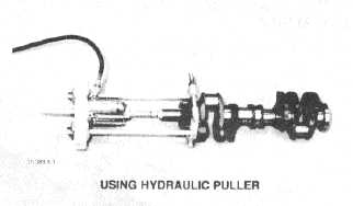
The IP820 Hydraulic Puller Group can also be used to
pull gear from crankshaft. Tools required are IP820
Hydraulic
Puller
Group,
8B7551
Bearing
Pulling
Attachment, 8B7549 Puller legs (two), 8B7561 Step
Plate, 3H465 Plate (four), IB4207 Nut (two), and 5P3100
Pump Group.
USING HYDRAULIC PULLER
CRANKSHAFT GEAR INSTALLATION
1. Install the key in keyway of crankshaft. Remove all
burrs from key and keyway inside of crankshaft gear.
2. Heat gear to 500°F (260°C) maximum.
3. Install gear on crankshaft with timing mark on gear
facing front of crankshaft.
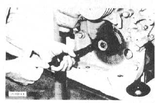
CRANKSHAFT FRONT OIL SEAL REMOVAL
Remote the crankshaft front pulley. Use the 1P3075
Puller Group to remove the crankshaft front oil seal.
REMOVING FRONT OIL SEAL
(Typical Example)
3-387