TM 5-3805-260-24
ference of 0.050 mm or more, do the Steps 15 through
19, .ADJUSTING FUEL PUMP CALIBRATION.
NOTE: The mechanic doing the checking must make
the decisions of which and how many pumps to check
according to the symptoms of the fuel injection pump
being tested.
14.
If dial indicator (4) readings for all the
pumps are within the limits in Step 13, the
calibration is acceptable. Remove the tooling,
and install the parts which were removed.
NOTE: For troubleshooting purposes, if the dial indicator
(4) reading is "0" or near "0", the calibration of the other
pumps is probably in the tolerance.
Adjustment of Fuel Pump Calibration
15.
Remove all pumps with 8S2243 Wrench.
16.
Clean the barrel and plunger of calibration
pump (1). Put clean diesel fuel on the
calibration pump (1) for lubrication.
17.
Install calibration pump (1) in the place of
one
of
the
pumps
according
to
the
procedure in Step 9.
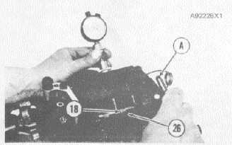
18. Loosen bolt (26) with 1S9836 Wrench (8) or
5P4206 Wrench. Turn the lever (18) on
shaft (24) enough to move the top of plunger
(28) of calibration pump (1) below top
surface (27) of calibration pump (1).Tighten
bolt (26) just enough for lever (18) to hold
plunger (28) stationary.
5P4206 WRENCH
18. Lever. 26. Bolt. A. 5P4206 Wrench.
NOTE: When bolt (26) has the correct torque, pushing
with a small amount of force on lever (18) through the
wrench moves plunger (28) up in calibration pump (1).
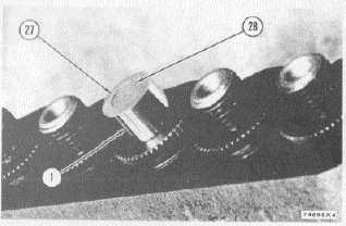
19. Move shaft (24) toward the governor to re-
move end play. Then push down on lever
(18).
through the wrench until top of plunger (28)
is almost even with top surface (27) of
calibration pump (1) as shown.
PLUNGER POSITION
1. Calibration pump. 27. Top surface of calibration
pump.28. Plunger.
20.
Check dial indicator (4) according to Step
10. Then put dial indicator (4) in place over the center of
calibration pump (1) and hold it there tightl5. Now move
plunger (28) of calibration pump (1) by pushing on lever
(18) through the wrench. Stop moving the plunger when
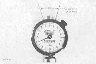
the dial indicator is at approximately 0.009 mm past
"0.000". Tighten bolt (26) to 24 + 2 lb. in. (2.8 + 0.2
Nm).
NOTE: When Moving plunger (28), make sure that the
last direction of plunger (28) movement is in the up
direction. If plunger (28) goes up too far, move plunger
(28) down to a position below that desired. Then move
plunger (28) up to the desired position
NOTE: The action of tightening bolt (26) usually
changes the reading on dial indicator (4) by ap-
proximately (0.010 mm) in the minus direction.
+ 0.010 mm CALIBRATION TOLERANCE
Move shaft (24) toward shutoff several times to
remove clearance in the linkage. Dial indicator (4)
2-62