TM 5-3800-205-23-1
AIR/HYDRAULIC BRAKE CYLINDER REPLACEMENT - CONTINUED
0086 00
REMOVAL - CONTINUED
4.
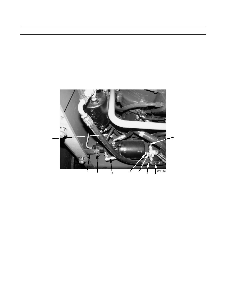
Disconnect hose (18) from elbow (14).
5.
Disconnect hoses (9, 10, and 11) from check valve (12).
6.
With assistance, remove two bolts (15) and washers (16) from bracket (17) and remove air/hydraulic cylinder (2) from
machine.
7.
Remove adapter (8), elbow (14), check valve (12), and adapter (13) from old cylinder (2).
9
18
13
17
12
15,16
14
11
10
INSTALLATION
1.
With assistance, position air/hydraulic cylinder (2) on bracket (17) and secure with two bolts (15) and washers (16).
2.
Connect hoses (9, 10, and 11) to check valve (12).
NOTE
Remove old antiseizing tape and apply new antiseizing tape to male threads of air system fitting before con-
nection is made.
3.
Connect hose (18) to elbow (14).
4.
Connect hose assembly (7) to adapter (8).
5.
Install wires (5) to overstroke indicator (6) with two lockwashers (4) and screws (3).
6.
Remove tags from wires (5).
7.
Connect brake tube assembly (1) to air/hydraulic cylinder (2).
0086 00-3


