TM 5-3800-205-23-1
FLYWHEEL MAINTENANCE - CONTINUED
0131 00
INSTALLATION - CONTINUED
1.
Install link and suitable lifting device to flywheel (5).
2.
Place flywheel (5) on guide bolt in same position as when removed. Align arrows on flywheel and crankshaft.
3.
Apply antiseize compound to threads of seven bolts (3) and install bolts and washers (4).
4.
Remove guide bolt.
5.
Apply antiseize compound to threads of top bolt (1) and install bolt and washer (2) on flywheel (5).
6.
Tighten bolts (1 and 3) evenly to 90 lb-ft (120 Nm).
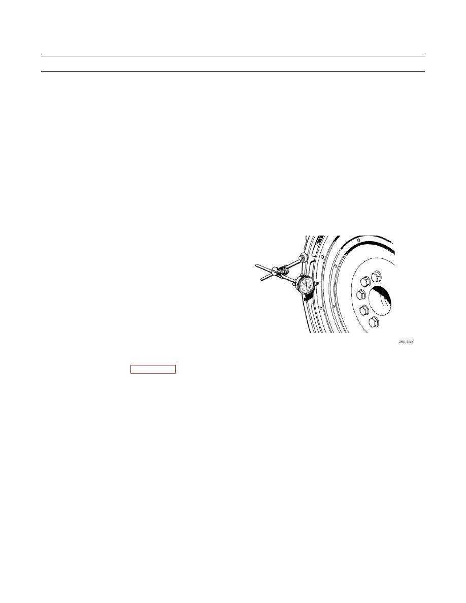
FLYWHEEL RUNOUT TEST
NOTE
Always apply force on crankshaft in same direction as rotation of flywheel before recording dial indicator
measurement. This will remove any crankshaft end clearance.
1.
Set dial indicator to 0.0 mm.
2.
Turn flywheel to intervals of 90, 180, 270, and 360
and observe and record dial indicator measurement at
each point.
3.
Difference between lower measurements and higher
measurements that are recorded at all four points must
not be more than 0.006 in. (0.15 mm).
4.
If more than 0.006 in. (0.15 mm) is observed at any of four test points, loosen and retorque bolts per Installation, step 6.
Repeat test.
5.
Install torque converter (WP 0146 00).
END OF WORK PACKAGE
0131 00-3


