TM 5-3800-205-23-1
INJECTOR SYNCHRONIZATION, FUEL SETTING, AND FUEL TIMING - CONTINUED
0140 00
FUEL TIMING - CONTINUED
11.
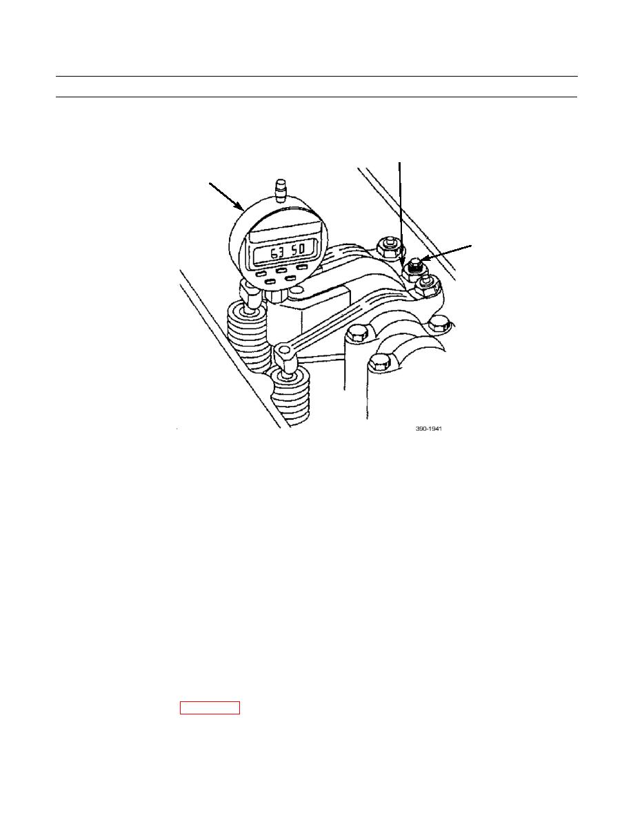
Remove indicator (35) and magnetic base from gage block (39) and carefully position it on top of tappet (40) for injector
(41) to be checked.
42
35
43
12.
Carefully position indicator contact point on shoulder of injector (41). Ensure indicator plunger moves freely and con-
tact point does not bind on injector spring.
NOTE
Refer to engine information plate, located at upper right-hand corner of valve cover, for correct fuel timing
setting. Setting must be within +/- 0.20 mm, as indicated on engine information plate.
13.
If indicator displays correct setting or is within +/- 0.20 mm checking tolerance, no adjustment is necessary. Go to step
16.
14.
If indicator does not indicate correct timing dimension, loosen locknut (42) for adjusting screw (43).
15.
Turn screw (43) until correct fuel timing is displayed on indicator. Tighten locknut (42) to 18 lb-ft (25 Nm) and check
adjustments again. If necessary, repeat this procedure until adjustment is correct.
16.
Sequence for checking fuel timing dimensions is as follows:
a.
Check and adjust fuel timing dimensions on half of cylinders with timing bolt installed.
b.
Remove timing bolt and indicator group.
c.
Rotate flywheel 360 and install timing bolt.
d.
Install indicator group and check/adjust fuel timing.
17.
Remove timing bolt from flywheel and install timing plug.
18.
Install front guard plate (WP 0100 00).
END OF WORK PACKAGE
0140 00-24


