TM 5-3805-248-23-2
STEERING CONTROL VALVE MAINTENANCE - CONTINUED
0312 00
TESTING RELIEF VALVE - CONTINUED
Part Number
Thickness
Change in Pressure
3H2549
0.010 in. (0.254 mm)
40 psi (276 kPa)
3J7473
0.005 in. (0.127 mm)
20 psi (138 kPa)
11.
Install new preformed packing (18) and plug (19).
NOTE
Repeat steps 3 through 11 to verify correct adjustment.
12.
Remove hydraulic pressure gage from steering control valve.
13.
Install new preformed packing (70) and plug (71).
14.
Adjust valve spool travel (WP 0175 00).
NOTE
This task can be made with one gage by testing steering cylinders one at a time. If only one hydraulic pres-
sure gage is used, remove only one of two valves at a time.
15.
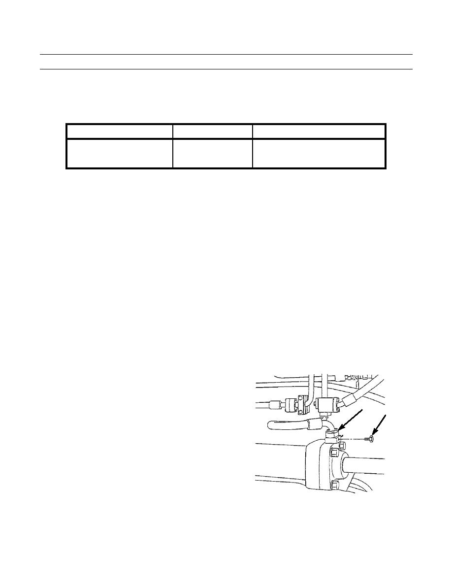
Remove two valves (75) from two steering cylinder blocks (74).
16.
Install two pressure gages into two steering cylinder blocks (74).
CAUTION
Do not turn steering wheel when the
engine is running and a low pressure
hydraulic pressure gage is installed in the
steering circuit. If the steering wheel is
74
turned, the pressure of the oil to the steer-
75
ing cylinders will be too high for a low
pressure hydraulic pressure gage.
17.
Operate engine (TM 5-3805-248-10).
18.
Test oil pressure. Gages must read between 40 and 70
psi.
19.
Record pressure. If the difference between the two
gages is more than 205 psi, refer to step 14 for adjust-
ing valve spool travel.
20.
Shut down engine (TM 5-3805-248-10).
394-984
21.
Remove two hydraulic pressure gages.
22.
Install two valves (75) and torque to 24 lb-ft (35 Nm).
0312 00-15


