TM 5-3805-260-24
adds to the pump oil in line (10) to elevator control valve
(12). With the engine running at high rpm and the valve
spool in control valve (12) in FORWARD position (C), the
oil from pump (22) goes through line (7) to run elevator
hydraulic motor (1) forward at high speed. The oil from
the elevator motor goes through line (8), control valve
(12) and through return oil line (13) into filter and tank
(19).
Move the elevator speed lever to the LOW position and
the valve spool in elevator speed valve (6) moves to
LOW SPEED position (L). Now, the oil from the cover
end of pump (22) goes through speed valve (6) and goes
into return oil line (13) to the tank. With only oil from one
section of pump (22) to elevator motor (1), the elevator
runs at a slow speed.
The elevator control lever must be moved to the HOLD
position to move the elevator valve spool to HOLD
position (B). With the valve spool in HOLD position, the
oil from pump (22) goes through control valve (12),
through return oil line (13) into filter and tank (19).
Elevator Reverse (No Illustration)
The elevator control lever is held in the REVERSE
position by the detent balls in elevator control valve (12).
With the valve spool in REVERSE position (A), the oil
from pump (22) goes through control valve ( 12) and
through line (8) to elevator motor (1) to run the elevator
in reverse. The oil from the elevator goes through line
(7), through control valve (12) and through return oil line
(13) into the filter and tank (19). The reverse speed of
the elevator is controlled by the rpm of the engine and
the position of the elevator speed lever connected to the
valve spool in elevator speed valve (6). HIGH SPEED
position (H) lets the oil from the cover end section of
pump (22) add to the oil from the drive end section of the
pump in line ( 10) to the elevator motor. The speed valve
stem in LOW SPEED position (L) lets the oil from the
cover end section of pump (22) go through return oil line
(13) to the tank. Now, only the oil from the drive end
section of the pump goes through line (10) and to the
elevator motor.
Move the control lever to the HOLD position. This moves
the elevator valve spool to HOLD position (B) and stops
the elevator.
ELEVATOR VALVES
Control Valve
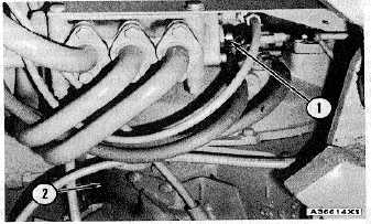
The location of the elevator control valve is just in front of
transmission (2), near the left side of the machine. The
flexible cable from the control lever goes under the
scraper hitch and is connected to valve spool (I) in the
elevator control valve.
ELEVATOR CONTROL VALVE
1. Valve spool (in control valve). 2. Transmission.
Detent balls, in the control valve, keep valve spool (1) in
any of the three positions for the valve spool. When the
valve spool is held in FORWARD position (C), the oil
from the pump goes in through inlet (6), opens check
valve (7),- goes through the check valve and through
outlet (4) that connects with an oil line to the elevator
hydraulic motor.
ELEVATOR CONTROL VALVE (HOLD POSITION)
1. Valve stem. 3. Outlet to tank. 4. Outlet to motor
(for reverse). 5. Outlet to motor (for forward). 6. Inlet
from pump. 7. Check valve. A. REVERSE position. B.
HOLD position. C. FORWARD position.
With valve spool (1) in HOLD position (B), the pump oil
through inlet (6) does not get any pressure to open
check valve (7) because the oil goes out through outlet
(3) and to the tank. The spring in check valve (7) keeps it
closed, when there is no pump oil pressure in the control
valve, and the oil in the lines to the elevator motor is
stopped. The hydraulic motor can not be turned when oil
is stopped in the lines to the motor.
With valve spool (1) in REVERSE position (A), the pump
oil through inlet (6) opens check valve (7) and then goes
through outlet (5) that connects with an oil line to the
elevator motor.
4-20


