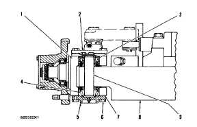
STEERING KNUCKLE (SIDE VIEW)
1.
Steering knuckle. 2. Upper cover assembly. 3. Upper
bearing. 4. Lower bearing. 5. Lower cover. 6. Bolts. 7. Shims. 8. Axle beam
assembly. 9. Kingpin.
6. Install lower cover (5) without shims and install and
tighten two opposite bolts (6) to a torque of 5. 7 N.
m (50 lb. in. ).
7. Use a feeler gauge to check the gap between the
cover and knuckle (I) at each bolt location.
8. Find the average of the two measurements and
subtract 0. 10 mm (. 004 in. ) from this average.
This is the thickness of shims (7) that must be
installed between lower cover (5) and the steering
knuckle.
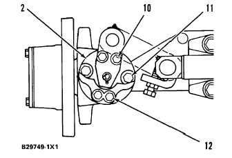
STEERING KNUCKLE (TOP VIEW)
2. Upper cover assembly. 10. Bolts. 11. Bolts. 12.
Bolts.
9. Remove the cover, install the shims, install cover (5)
and the bolts. To check the preload adjustment of
the bearings, use the procedure that follows:
TM 5-3805-260-24
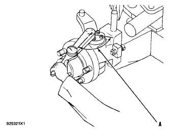
1. Put a pound-inch torque wrench on one of the upper
cover bolts so that the handle of the wrench is angle
(A) 900 from the center of the bolt directly opposite
the bolt that the torque wrench is on.
2. Check the torque required to turn the steering
knuckle.
NOTE: The steer wheel and steering link must be
removed before the check is made.
3. The indication must be 4. 5 to 6. 8 N. m (40 to 60 lb.
in. ). If the indication is too high, add shims
between the lower cover and knuckle. If the
indication is too low, shims must be removed.
5-9
TM 5-3805-260-24