TM 5-3800-205-23-1
INJECTOR SYNCHRONIZATION, FUEL SETTING, AND FUEL TIMING - CONTINUED
0140 00
INJECTOR SYNCHRONIZATION - CONTINUED
NOTE
Push indicator plunger in and out to ensure travel direction is correct. Indicator should indicate positive
(+) when plunger moves out.
Ensure indicator has adequate travel in both directions. Reposition indicator to allow for travel in both
directions, if required.
13.
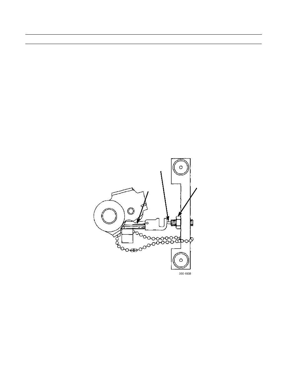
Adjust spring plunger for correct travel:
a.
Rotate control rod (7) in "B" direction until linkage hits stop.
b.
Rack head (10) of injector body (8) should now have fully compressed spring plunger (17).
c.
Press ZERO button on indicator (13).
d.
Allow control rod (7) to rotate back in "A" direction until injector rack head stop pin (9) is against sync gage block
(11).
e.
Indicator should indicate between 1.25 and 2.25 mm. If indication is not between 1.25 and 2.25 mm, loosen lock-
nut (18) on spring plunger (17) and reposition plunger until between 1.25 and 2.25 mm is indicated.
17
18
9
0140 00-7


