TM 5-3805-248-23-2
SCRAPER CONTROL VALVE REPLACEMENT - CONTINUED
0323 00
TESTING AND ADJUSTMENT - CONTINUED
Sequence Valve - Continued
7.
Remove plug (13), piston (12), shims (10) and (11), spring (14) and valve (9).
8.
Add or remove shims (10) and (11). Decrease shim(s) thickness to lower pressure. Increase shim(s) thickness to raise
pressure. Refer to following chart to determine the correct amount of shim(s) to be added or removed.
Table 1. Pressure Change to Relief Valve by Removal or Addition of One Shim.
Part Number
Thickness
Change in Pressure
3J7473
0.005 in. (0.127mm)
90 psi (621 kPa)
3H2549
0.010 in. (0.254 mm)
175 psi (1,207 kPa)
9.
Install valve (9), spring (14), shims (10) and (11), pis-
9
ton (12) and plug (13).
5
10.
Start engine. Check gage (8). If reading is correct,
remove gage and install plug (5). If reading is not cor-
rect, repeat steps 4 through 9.
14
10,11
12
13
394-1061
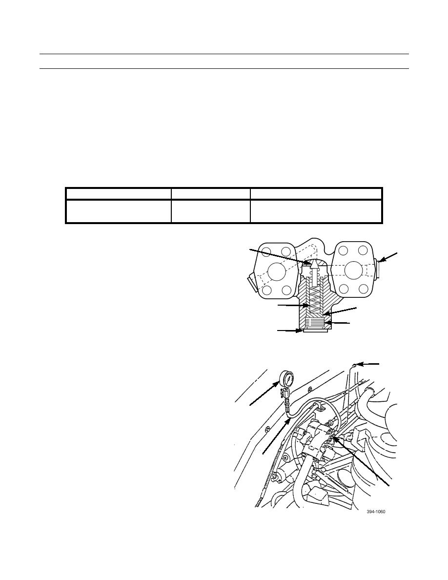
Ejector Kickout Valve
5
1.
Position ejector gate return lever to full forward posi-
tion.
2.
Remove plug (5).
3.
Install adapter (6).
8
4.
Install hose (7) and gage (8).
7
6
0323 00-4


