TM 5-3805-260-24
BRAKE HEAD ASSEMBLIES
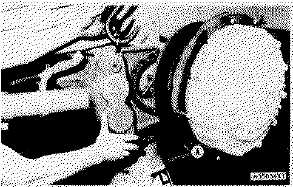
5. Remove the eight bolts that hold the brake head assembly
to the axle housing.
NOTE: The center two bolts can not be removed completely
because of the clearance between the brake head assembly
and the brake line guard. Remove these bolts with the brake
head assembly.
6. Remove the brake head assembly. Weight of the brake
head assembly is 90 lb. (41 kg).
CAUTION: The two anchor pins and brake linings are free to
fall out of the brake head assembly and must be held in
position.
INSTALL BRAKE HEAD ASSEMBLIES
Tools Needed
A
8S7640
Stand
1
8S7611
Tube
1
8S7615
Pin
1
8S8048
Saddle
1
1. Fasten a hoist to the brake head assembly with two 3/8"-
16 NC forged eyebolts.
2. Put two of the bolts that hold the brake head assembly to
the axle housing in the center two holes of the brake
head assembly bracket.
CAUTION: Make sure the two anchor pins and brake linings
are held in position when the brake head assembly is
installed.
3. Put the brake head assembly in position on the machine
and tighten the bolts to a torque of 225 25 lb.ft. (300
35 N.m).
4. Remove the forged eyebolts and hoist from the brake
head assembly.
5. Push the anchor pins into the brake head assembly. Make
sure there is .010 in. (0.25 mm) or more distance
between the anchor pins and wheel disc. Install the two
bolts to hold the anchor pins.
6. Connect the brake line to the brake head assembly.
7. Remove (bleed) the air from the hydraulic brake system.
See AIR REMOVAL FROM BRAKES in TESTING AND
ADJUSTING.
8. Remove tooling (A). Put into position the hydraulic jack
used to lift the machine for tire installation.
end by:
a) install rim and tire (tractor or scraper)
3-287