
TM 5-2350-377-13&P
0012
ELECTRICAL SYSTEM - Continued
STEP
9.
Check control box for continuity.
a.
Push right side track tensioning switch (Figure 7, Item 4) up.
b.
Check continuity between connector pins on connectors J-1 (Figure 7, Item 3) and J-2
(Figure 7, Item 2).
c.
Release right side track tensioning switch (Figure 7, Item 4).
d.
Refer to Table 4 for lead locations.
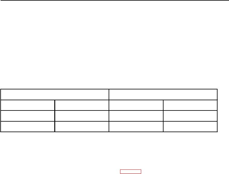
Table 4.
Control Box Right Side Tension Switch.
POSITIVE LEAD
NEGATIVE LEAD
J-1 (4)
J-2 (3)
J-1 (4)
J-2 (3)
C
D
D
D
CONDITION/INDICATION
Is continuity present at right side track tensioning switch?
DECISION
YES - If continuity is indicated, go to Step (10).
NO - If an open circuit is indicated, replace control box (WP 0028). Verify problem is solved.
STEP
10.
Check control box for continuity.
a.
Push track loosening switch (Figure 7, Item 1) up.
b.
Check continuity between connector pins on connectors J1 (Figure 7, Item 3) and J2 (Figure 7, Item 2).
c.
Refer to Table 5 for lead locations.
d.
Release the track loosening switch (Figure 7, Item 1).