TM 5-2350-377-13&P
0012
ELECTRICAL SYSTEM - Continued
STEP
12.
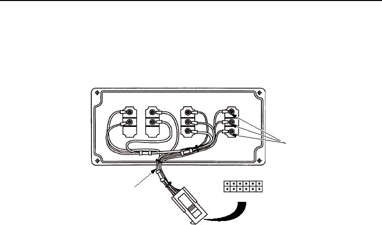
Check control box switches for continuity.
a.
Remove control box wiring harness (Figure 9, Item 2) from switch connector pins (Figure 9, Item 1).
SW1
SW2
SW3
SW4
1
1
1
1
2
2
2
2
3
3
1
123456
2
7 8 9 10
T00409HBF
Figure 9. Control Box Wiring Harness.
b.
Check continuity between switch connector pins.
c.
Refer to Table 7 for lead locations.
03/15/2011Rel(1.8)root(tswp)wpno(T00004)

