
TM 5-2350-377-13&P
FIELD MAINTENANCE
DOZER BLADE REPLACEMENT AND REPAIR
INITIAL SETUP:
Materials/Parts (cont.)
Tools and Special Tools
Tool Kit, General Mechanic's: Automotive
Nut, Self-Locking (WP 0057, Figure 12, Item 52)
(WP 0071, Table 1, Item 7)
Qty: 2
Bolt, Eye (WP 0071, Table 1, Item 1)
Washer, Lock (WP 0057, Figure 12, Item 54)
Chain Assembly (WP 0071, Table 1, Item 2)
Qty: 4
Lifting Device, Minimum Capacity 1,000 lb (454 kg)
Personnel Required
Materials/Parts
Construction Equipment Repairer, 91L
Grease, Automotive and Artillery (GAA)
(WP 0070, Table 1, Item 13, 14, 15, 16, 17)
Equipment Condition
Front of vehicle blocked (TM 5-2350-262-20)
Dozer blade folded (WP 0005)
Dozer cutting edge removed or dozer blade
extensions removed (TM 5-2350-262-20)
REMOVAL
NOTE
New production vehicles are equipped with a steel dozer blade which includes a cut-out and
cover at top rear of dozer blade. Perform Step (1) if removing cover.
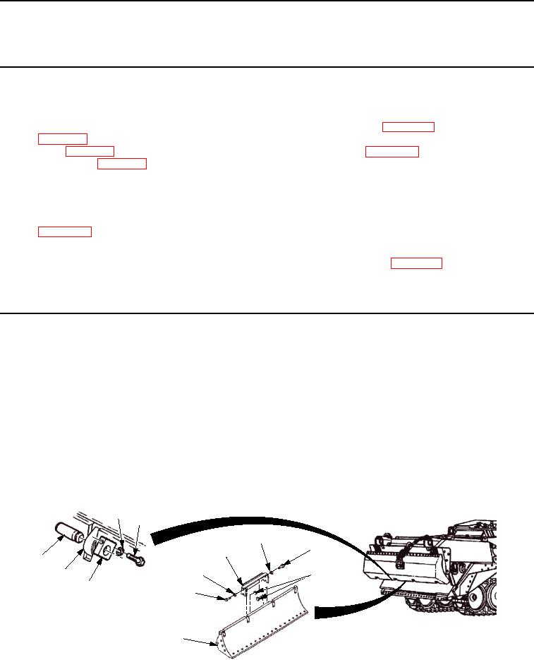
1.
Remove two screws (Figure 1, Item 5), washers (Figure 1, Item 3), locknuts (Figure 1, Item 6), and cover
(Figure 1, Item 4) from dozer blade (Figure 1, Item 7). Discard locknuts.
2.
Remove two screws (Figure 1, Item 2) and washers (Figure 1, Item 1) from dozer blade (Figure 1, Item 7) and
two inner pivot pins (Figure 1, Item 9).
3.
Using hammer and brass drift, remove two inner pivot pins (Figure 1, Item 9) from dozer blade
(Figure 1, Item 7) and apron (Figure 1, Item 8).
1
2
3
5
4
9
3
8
6
7
5
7
M0044HBF
Figure 1.
Inner Pivot Pins Removal.
03/15/2011Rel(1.8)root(maintwp)wpno(M00010)