TM 5-2350-377-13&P
0041
INSTALLATION (LEFT SIDE) - Continued
2
2
3
1
24
3
22
4
23
22
25
6 5
REAR
VIEW
8
7
21
20
9
10
11
1
12
13
9
14
14
15
8
16
8
9
17
19
18
M0062HBF
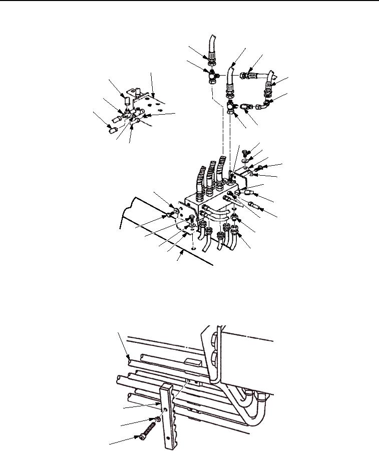
Figure 5.
Manifold Tubes Installation.
19.
From hull access opening, secure seven tubes (Figure 6, Item 1) to hull with retaining strap (Figure 6, Item 4),
two washers (Figure 6, Item 3), and screws (Figure 6, Item 2).
1
4
3
2
M0063HBF
Figure 6.
Manifold Tubes Installation.
END OF TASK
03/15/2011Rel(1.8)root(maintwp)wpno(M00013)

