
TM 5-3800-205-23-1
HYDRAULIC TANK SAFETY RELIEF VALVE ASSEMBLY MAINTENANCE
THIS WORK PACKAGE COVERS
Removal, Disassembly, Cleaning and Inspection, Assembly, Installation
INITIAL SETUP
Equipment Condition
Maintenance Level
Unit
Machine parked on hard, level surface (TM 5-380-
205-10-1 or TM 5-3800-205-10-2)
Tools and Special Tools
Tool kit, general mechanic's (Item 33, WP 0172
Scraper bowl or water tank lowered to ground (TM
5-380-205-10-1 or TM 5-3800-205-10-2)
Materials/Parts
Parking brake applied (TM 5-380-205-10-1 or TM
5-3800-205-10-2)
Detergent (Item 11, WP 0171 00)
Oil, lubricating (Item 24 or 29, WP 0171 00)
Wheels chocked (TM 5-380-205-10-1 or TM 5-
3800-205-10-2)
Rag, wiping (Item 31, WP 0171 00)
O-ring (3)
Battery disconnect switch in OFF position (TM 5-
380-205-10-1 or TM 5-3800-205-10-2)
Ring, retaining
WARNING
Do NOT disconnect or remove any hydraulic system line or fitting unless engine is shut down and hydraulic
system pressure has been relieved. Tighten all connections before applying pressure. Escaping hydraulic
fluid under pressure can penetrate the skin, causing serious injury.
REMOVAL
1.
Relieve hydraulic system pressure by moving control
levers through all positions (TM 5-3800-205-10-1 or
1
TM 5-3800-205-10-2).
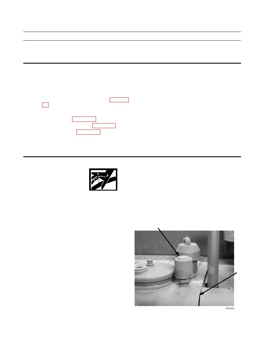
2.
Remove relief valve (1) assembly from top of hydrau-
lic tank (2).
2
