TM 5-3805-248-23-1
MECHANICAL STEERING ASSEMBLY ADJUSTMENT - CONTINUED
0175 00
ADJUSTMENT - CONTINUED
NOTE
Step 19 requires assistance.
19.
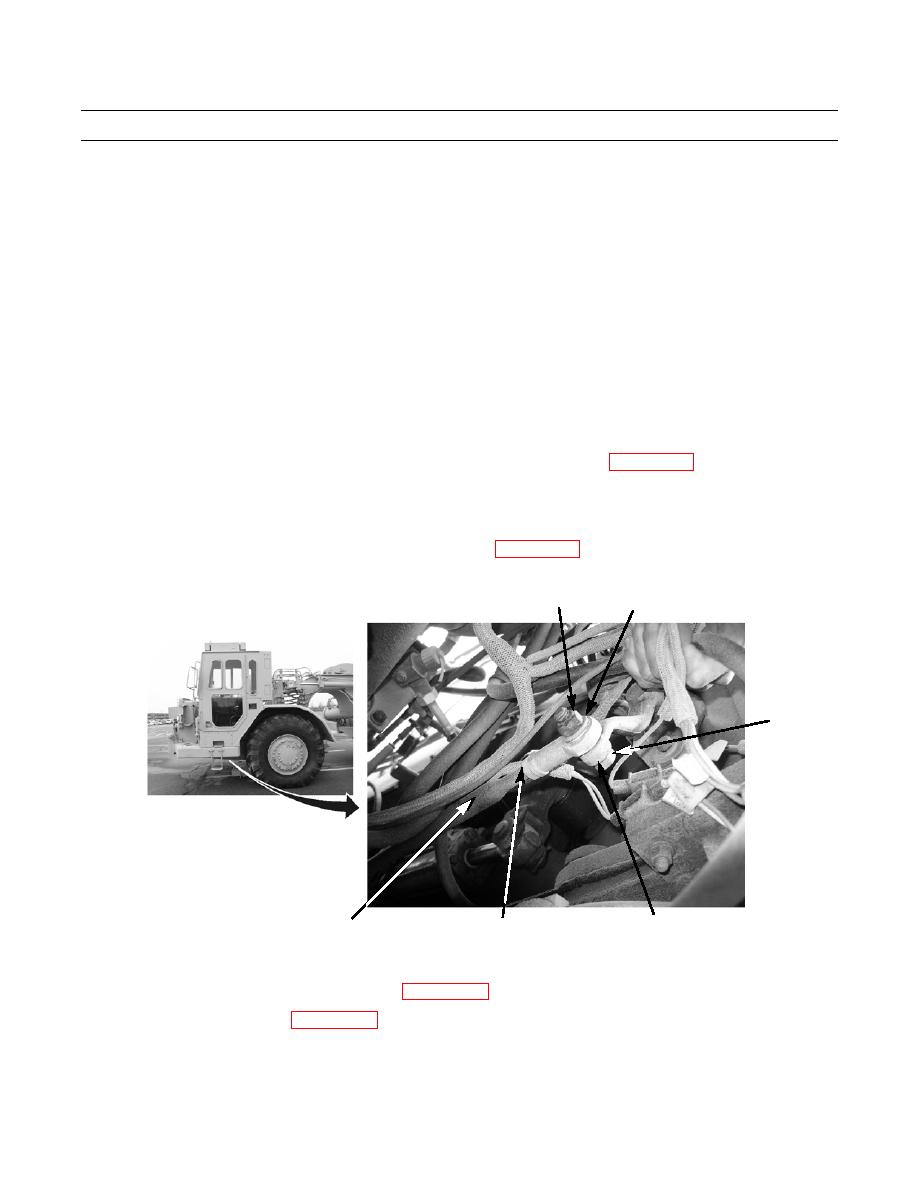
Center position of lever (4). With assistance, turn the steering wheel, while measuring full travel of lever (4) to locate its
center point.
CAUTION
Do not push or pull on rod assembly. This will cause movement of valve spool. Do not force bolt through
rod assembly and lever. If bolt does not fit through hole in rod assembly and lever, proceed with the follow-
ing steps.
20.
Loosen jamnut.
21.
Turn rod end in or out to align hole in rod end with hole in lever (4). Torque IAW (WP 0335 00).
22.
Tighten jamnut.
23.
Position rod assembly and lever (4) together with holes aligned.
24.
Install bolt (3), washer (2) and nut (1) on lever (4) torque IAW (WP 0335 00).
1
2
3
394-448
4
JAMNUT
ROD ASSEMBLY
25.
Recheck travel of steering control valve spool. Refer to step 1.
26.
Install operator compartment front access plate (WP 0197 00).
27.
Install front crankcase guard (WP 0201 00).
END OF WORK PACKAGE
0175 00-5/(-6 blank)


