TM 5-3805-260-24
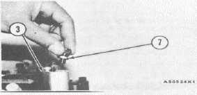
3. Put adapter (3) and spring (4) over zero set pin
(5). Use a I D4533 Bolt and a ID4538 Bolt to
fasten adapter (3) to the housing for the fuel
injection pumps.
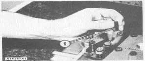
4. Put screw (6) in the hole over pin (5) and spring
(4).
INSTALLATION OF SCREW
6. 8S7271 Screw.
5. Turn screw (6) clockwise until pin (5) is held
against the housing for the fuel injection
pump. DO NOT tighten screw (6) too tight.
6. Put clamp (7) in adapter (3).
7. Move the governor control lever to FULL. LOAD
position.
INSTALLATION OF CLAMP
3. Adapter. 7. 3P1565 Collet clamp.
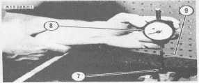
8. Put 5P6531 Point (9) on dial indicator (8). Put the
indicator assembly in clamp (7).
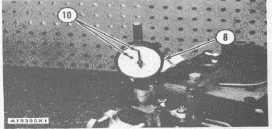
9. Adjust dial indicator (8) so both pointers (10) are
on "O" (zero).
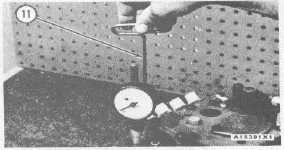
10. Use French (11) to turn the 8S7271 Screws (6)
counter clockwise. Turn screws (6) six or
more turns.
11. Put the clip end of the 8S4627 Circuit Tester to a
good ground. Put the other end of the
8S4627 Circuit Tester on the load stop
contact.
INSTALLATION OF DIAL INDICATOR
7. 3P1565 Collet Clamp.8. 3P1567 Dial Indicator.9.
5P6531 Contact Point, 2.25 In. (57.2 mm) long.
INDICATOR SET ON ZERO
8. 3P1567 Dial Indicator. 10. Pointers.
LOOSENING SCREW (6)
11. 5P4205 Wrench.
12. Move the governor control lever to the LOW
IDLE position.
13. Move the governor control lever slowly toward
the HIGH IDLE position until the continuity
light just comes on. Make a note of the
reading on dial indicator (8). Do this step
several times to make sure the reading is
correct.
2-54