TM 5-3805-260-24
CAB
13.
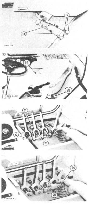
Put cables (18) in position through cab and install the
rubber protectors, the extensions and nuts (17). Install
lower cable on the lever. Install the pin through the lever.
Install the top cable as shown. To adjust linkage, see
LINKAGE ADJUSTMENTS FOR THE TRANSMISSION
HYDRAULIC
CONTROLS
in
POWER
SHIFT
TRANSMISSION, TESTING AND ADJUSTING.
14.
Install seat (19) in the cab and connect seat belt (20) to
the eyebolts.
15.
Install four nuts (21), rubber protectors, extension (23)
and four nuts (22) to the cables.
16.
Install links (25) and angle (24). Install the nuts on the
ends of the cables.
NOTE: Use nuts (22) to adjust the leers in their correct
vertical position.
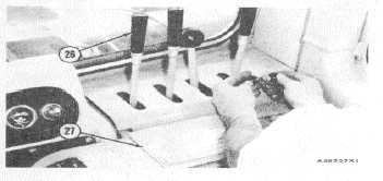
17.
Install cover assembly (27) and knobs (26).
3-331