TM 5-2350-377-13&P
0043
REMOVAL - Continued
NOTE
There is an additional clamp on left hydraulic track adjusting cylinder.
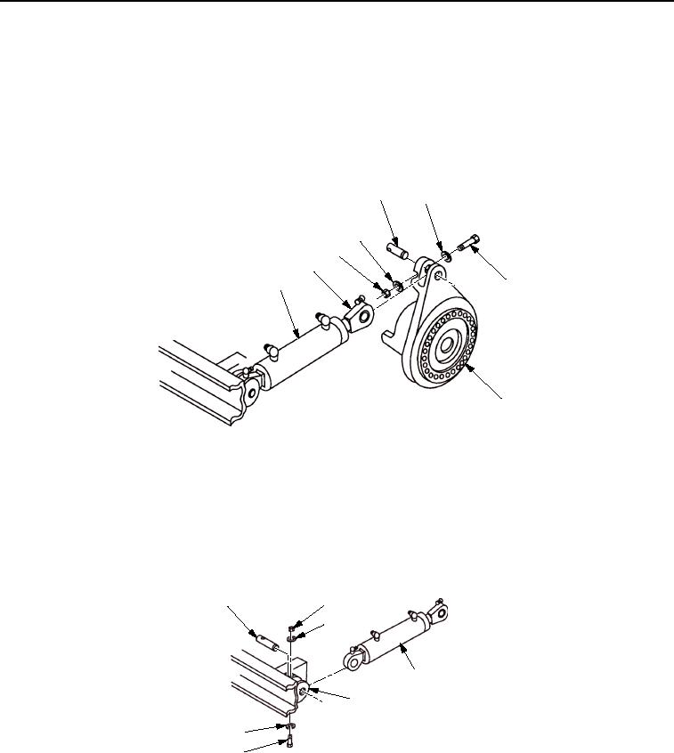
2.
Remove screw (Figure 2, Item 6), washers (Figure 2, Item 4), locknut (Figure 2, Item 3), and pin
(Figure 2, Item 5). Disconnect rod end (Figure 2, Item 2) of hydraulic track adjusting cylinder
(Figure 2, Item 1) from final drive adjusting flange (Figure 2, Item 7). Discard locknut.
5
4
4
3
2
1
6
7
M0074HBF
Figure 2. Final Drive Adjusting Flange Removal.
NOTE
Screw must be removed from bottom when connecting fixed end of cylinder to hull.
3.
Remove screw (Figure 3, Item 6), washers (Figure 3, Item 3), locknut (Figure 3, Item 2), pin
(Figure 3, Item 1), and fixed end of track adjusting cylinder (Figure 3, Item 4) from hull mounting bracket
(Figure 3, Item 5). Discard locknut.
1
2
3
4
5
3
6
M0075HBF
Figure 3. Track Adjusting Cylinder Rod End Removal.
END OF TASK
03/15/2011Rel(1.8)root(maintwp)wpno(M00015)

