TM 5-3805-248-23-2
CRANKSHAFT MAIN BEARINGS MAINTENANCE - CONTINUED
0347 00
END BEARINGS ADJUSTMENT - CONTINUED
6.
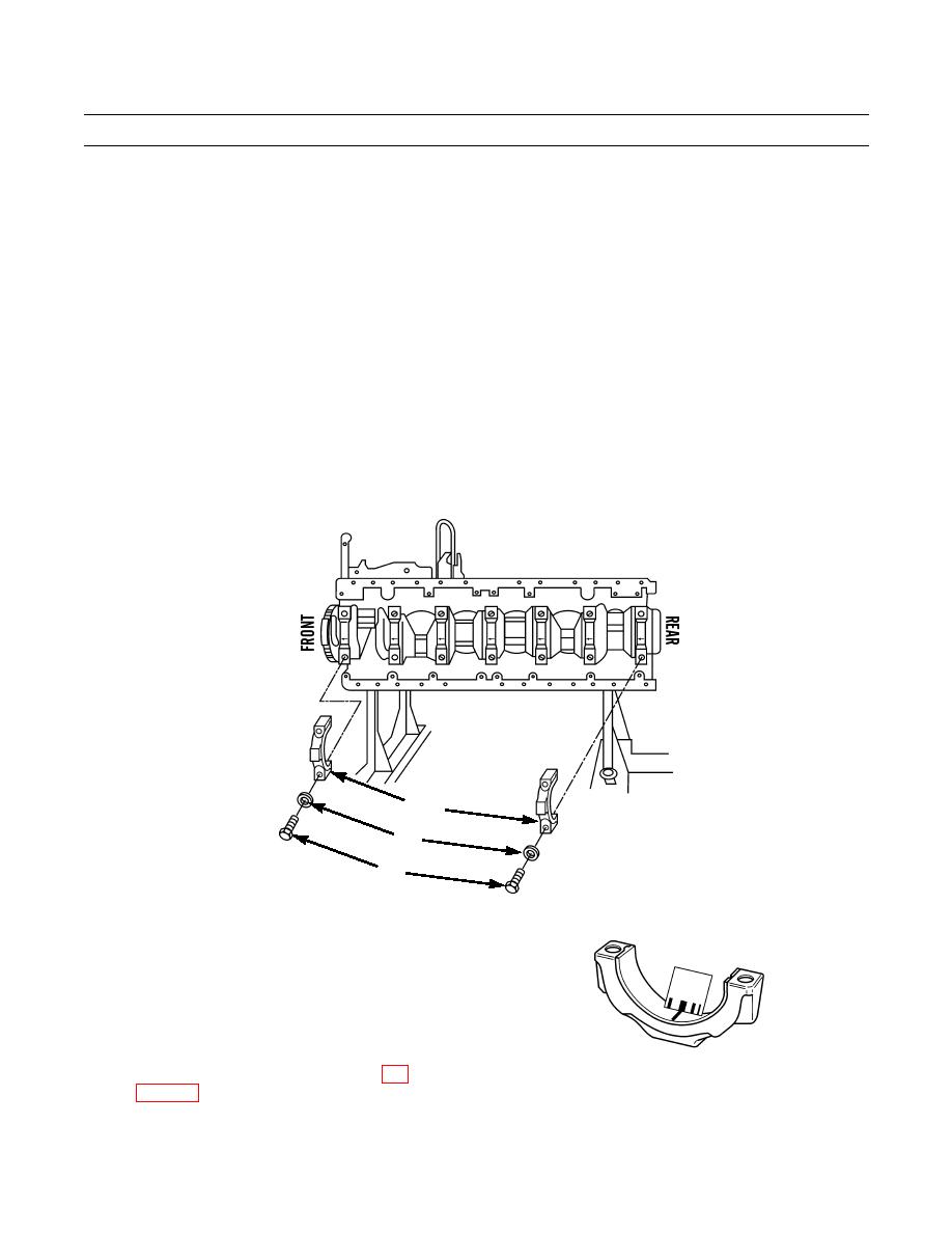
Position two new lower half main bearings (11) in bearing caps (12).
7.
Position bearing clearance gage 1-1/2 in. long on surface of each of two new lower half main bearings (11).
8.
Position two bearing cap (12) assemblies and bearing clearance gage on crankshaft, and align holes in bearing caps (12)
with holes in cylinder block.
9.
Use clean engine oil to lubricate four bolts (14).
10.
Install and hand-tighten four bolts (14).
11.
Torque two bolts (14) at bearing tab side of bearing caps (12) to 190 lb-ft (258 Nm).
12.
Torque two bolts (14) opposite bearing tab side of bearing caps (12) to 190 lb-ft (258 Nm).
13.
Use chalk to mark four bolts (14) and two bearing caps (12).
14.
Tighten two bolts (14) opposite tab side of bearing caps (12) 120 degrees.
15.
Tighten two bolts (14) at bearing tab side of bearing caps (12) 120 degrees.
16.
Remove four bolts (14) and two bearing cap (12) assemblies from crankshaft.
11,12
13
14
394-1152
17.
Use the scale provided to measure thickness of each
bearing clearance gage. Record measurement.
NOTE
Thickness of bearing clearance gage must
be within range of 0.0037-0.0068 in.
(0.005-0.009 mm). If measurement
394-1151
exceeds this range, replace crankshaft (WP
Installation.
0347 00-13


