TM 5-3805-260-24
DIFFERENTIAL AND CARRIER ASSEMBLY
REMOVE DIFFERENTIAL AND CARRIER ASSEMBLY
Tools Needed
A
B
8S7620
Base Assembly
2
BS7650
Cylinder
2
8S7645
Hose Group
1
5P3100
Pump Group
1
8S7640
Stand
2
8S7611
Tube
2
8S7615
Pin
2
8S8048
Saddle
2
start by:
a)
remove crankcase guard*
b)
remove lower drive shaft
1.
Put blocks under the scraper wheels for safety.
2.
Drain the oil from the differential and both final drive
compartments. The total capacity is 8 U.S. gal.
(30.3 litre).
3.
Remove the final drive covers and move each axle
out approximately 12 in. (30 cm).
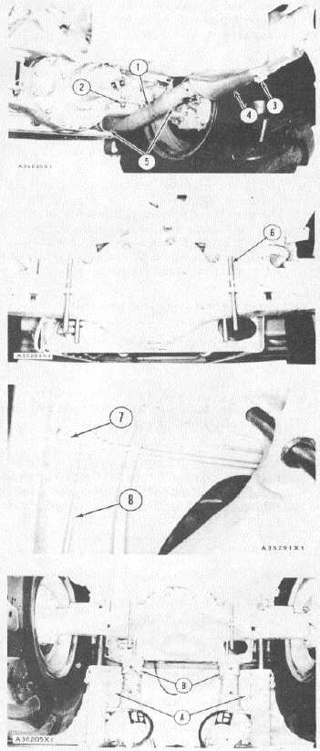
4.
Remove the bolts from clamps (3) and (5). Remove
muffler (4) and tube (1).
5.
Remove eight nuts (2) from the bolts that hold the
axle housing to the frame.
6.
Use .75 in. (19.1 mm) diameter steel rod and make
four 15 in. (38.1 cm) long guide pins. Put 3/4"-16
NF threads on one end of the guide pins and install
a nut to make guide bolts.
7.
Make a replacement of four of the bolts that hold
the axle housing to the frame with the fabricated
guide bolts (6) as shown.
8.
Remove bolt (7) from the assembly. Remove the
bolt from the clip that holds right wheel brake line
(8) to the frame above the axle housing.
9.
Use tooling (A) to lift the machine approximately 4
in. (10.2 cm).
10.
Install tooling (B) under the frame as shown.
*This operation is in the ENGINE DISASSEMBLY
AND ASSEMBLY.
3-228